NetVanta 1000 Series
To the Holder of the Manual
Trademarks
Software Licensing Agreement
Conventions
Safety Instructions
Save These Important Safety Instructions
FCC-Required Information
REN/SOC FIC Usoc
FCC Radio Frequency Interference Statement
Electromagnetic Compatibility EMC Table
Wireless Radio Channel Ranges
Service and Warranty
Table of Contents
Copyright 2008 ADTRAN, Inc
List of Figures
Copyright 2008 ADTRAN, Inc
List of Tables
Copyright 2008 ADTRAN, Inc
Wireless Access
Power over Ethernet
SFP Module Slots
NetVanta
NetVanta 1224 Shipping Contents
NetVanta 1224 Front Panel Design
NetVanta 1224 Rear Panel Design
Power Connection
Status LED
NetVanta 1224ST
NetVanta 1224ST Shipping Contents
NetVanta 1224ST Front Panel Design
NetVanta 1224ST Rear Panel Design
Gigabit Ethernet Interfaces/SFP Slots
NetVanta 1224R
NetVanta 1224ST Rear Panel Interfaces Console Interface
NetVanta 1224R Shipping Contents
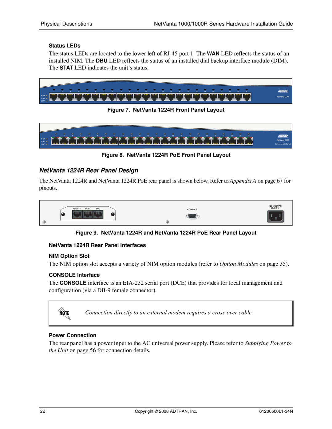
NetVanta 1224R Front Panel Design
NetVanta 1224R Rear Panel Design
Status LEDs
NetVanta 1224STR Shipping Contents
NetVanta 1224STR
NetVanta 1224STR Front Panel Design
NetVanta 1224STR Rear Panel Design
NetVanta 1224STR AC Front Panel Layout
NetVanta
NetVanta 1335 Shipping Contents
NetVanta 1335 Front Panel Design
Gigabit Ethernet Interfaces/SFP Slots
NetVanta 1335 Rear Panel Design
NetVanta 1335 Front Panel Layout
NetVanta 1335 Rear Panel Interfaces NIM Option Slot
Antenna Connectors
NetVanta 1524ST
CompactFlash
NetVanta 1524ST Shipping Contents
NetVanta 1524ST Front Panel Design
NetVanta 1524ST Rear Panel Design
CSMA/CD
Power over Ethernet
Front Panel LED Descriptions
Product Specifications
Option Modules
Network Interface Modules
NetVanta 56K/64K NIM P/N 1200861L1
NetVanta T1/FT1 NIM P/N 1202862L1
T1/FT1 Interface
NetVanta T1/FT1 Nebs NIM P/N 1200862L2#NEBS
NetVanta T1/FT1 Nebs NIM
NetVanta T1/FT1 + DSX-1 NIM P/N 1202863L1
DSX-1 Interface
NetVanta Dual T1 NIM P/N 1200872L1
T1 Interface
NetVanta E1/FE1 NIM P/N 1200868E1/L1
WAN-E1 Interface
NetVanta E1/FE1 + G.703 Drop NIM P/N 1200878E1/L1
Interface
NetVanta Serial NIM P/N 1200866E1
Operating Mode
Serial Interface
NetVanta Shdsl NIM, Annex a P/N 1200936E1
Shdsl Interface
NetVanta Shdsl NIM, Annex B P/N 1200937E1
NetVanta Shdsl NIM, Annex B
NetVanta Adsl NIM, Annex a P/N 1202869E1
Adsl Interface
NetVanta Adsl NIM, Annex B P/N 1202889E1
NetVanta Adsl NIM, Annex B
NetVanta 3G Cdma NIM P/N 1700801G1
Wireless Technologies
Frequency Bands
Cdma NIM LED Descriptions LED Label LED Color Indication
1xRTT
Features
Dial Backup Interface Modules
NetVanta Analog Modem DIM P/N 1200864L1
NetVanta Isdn BRI DIM P/N 1200865L1
NetVanta Isdn S/T DIM P/N 1200875L1
Etsi TBR
Unit Installation
Tools Required
Rack Mounting the NetVanta
Mounting Options
Instructions for Rack Mounting the NetVanta Step Action
Instructions for Wall Mounting the NetVanta
Wall Mounting the NetVanta
Step Action
NetVanta 1000 and 1000R Series AC-Powered Units
Supplying Power to the Unit
NetVanta 1224STR DC
Installing Dial Backup and Network Interface Modules
Grounding the NetVanta 1224STR DC
Instructions for Installing the DIMs Step Action
Installing DIMs
Instructions for Installing the NIMs Step Action
NIM and DIM Installation
NetVanta VPN Accelerator Card Installation
Installing a CompactFlash Card NetVanta 1335 Series only
Instructions for Installing a CompactFlash Card Step Action
Instructions for Installing Antennas Step Action
Installing the 3G Cdma NIM Antennas
Notification for Devices with Detachable Antennas
Description
Diversity Antenna Specifications Description
Maximum Unit
Antenna Extensions
Additional Warnings
Antenna Installation Instructions
Instructions for Installing the 3G NIM Antennas
Copyright 2008 ADTRAN, Inc
Table A-2. SFP Slot Pinouts
Table A-1. Console Port Pinouts Name Description
Pin Name
Pin Name Description
Table A-3 /100Base-T Ethernet Port Pinouts
Table A-4 Base-T Gigabit Ethernet Port Pinouts
Table A-6. WAN-T1 Connector Pinouts
Table A-5. WAN-DDS Connector Pinouts Name Description
Table A-7. WAN-E1 Connector Pinouts
Table A-9. G.703 Connector Pinouts Name Description
Table A-8. DSX-1 Connector Pinouts Name Description
Table A-10. WAN-SHDSL Connector Pinouts
Table A-11. WAN-ADSL Connector Pinouts
Table A-12. Serial to Cable Connector Pinouts EIA
Pin
Dial Backup Interface Module Pinouts DBU Connector
Table A-15. Isdn S/T DBU Connector Pinouts
Copyright 2008 ADTRAN, Inc
Index
Numerics
Index NetVanta 1000/1000R Series Hardware Installation Guide