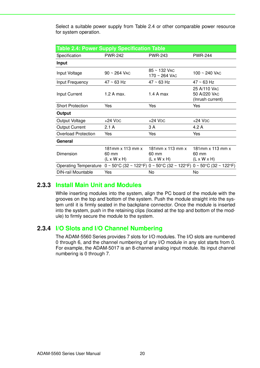
Select a suitable power supply from Table 2.4 or other comparable power resource for system operation.
Table 2.4: Power Supply Specification Table
Specification | ||||
Input |
|
|
| |
|
|
|
| |
Input Voltage | 90 ~ 264 VAC | 85 ~ 132 VAC | 100 ~ 240 VAC | |
170 ~ 264 VAC | ||||
|
|
| ||
Input Frequency | 47 ~ 63 Hz | 47 ~ 63 Hz | 47 ~ 63 Hz | |
Input Current | 1.2 A max. | 1.4 A max | 25 A/110 VAC | |
50 A/220 VAC | ||||
|
|
| (Inrush current) | |
Short Protection | Yes | Yes | Yes | |
Output |
|
|
| |
|
|
|
| |
Output Voltage | +24 VDC | +24 VDC | +24 VDC | |
Output Current | 2.1 A | 3 A | 4.2 A | |
Overload Protection | Yes | Yes | Yes | |
General |
|
|
| |
|
|
|
| |
| 181mm x 113 mm x | 181mm x 113 mm x | 181mm x 113 mm x | |
Dimension | 60 mm | 60 mm | 60 mm | |
| (L x W x H) | (L x W x H) | (L x W x H) | |
Operating Temperature | 0 ~ 50°C (32 ~ 122°F) 0 ~ 50°C (32 ~ 122°F) 0 ~ 50°C (32 ~ 122°F) | |||
Yes | No | No | ||
2.3.3Install Main Unit and Modules
While inserting modules into the system, align the PC board of the module with the grooves on the top and bottom of the system. Push the module straight into the sys- tem until it is firmly seated in the backplane connector. Once the module is inserted into the system, push in the retaining clips (located at the top and bottom of the mod- ule) to firmly secure the module to the system.
2.3.4I/O Slots and I/O Channel Numbering
The
20 |
