The system can also be secured to the cabinet by using mounting rails. If you mount the system on a rail, you should also consider using end brackets at each end of the rail. The ended brackets help keep the system from sliding horizontally along the rail. This minimizes the possibility of accidentally pulling the wiring loose. If you examine the bottom of the system, you will notice two small retaining clips. To secure the sys- tem to a DIN rail, place the system on to the rail and gently push up on the retaining clips. The clips lock the system on the rail. To remove the system, pull down on the retaining clips, lift up on the base slightly, and pull it away from the rail.
2.3.6Jumper and DIP Switch Settings
This section tells you how to set the jumpers and DIP switches to configure your
2.3.6.1RS-232/485 Selectable Jumper Setting
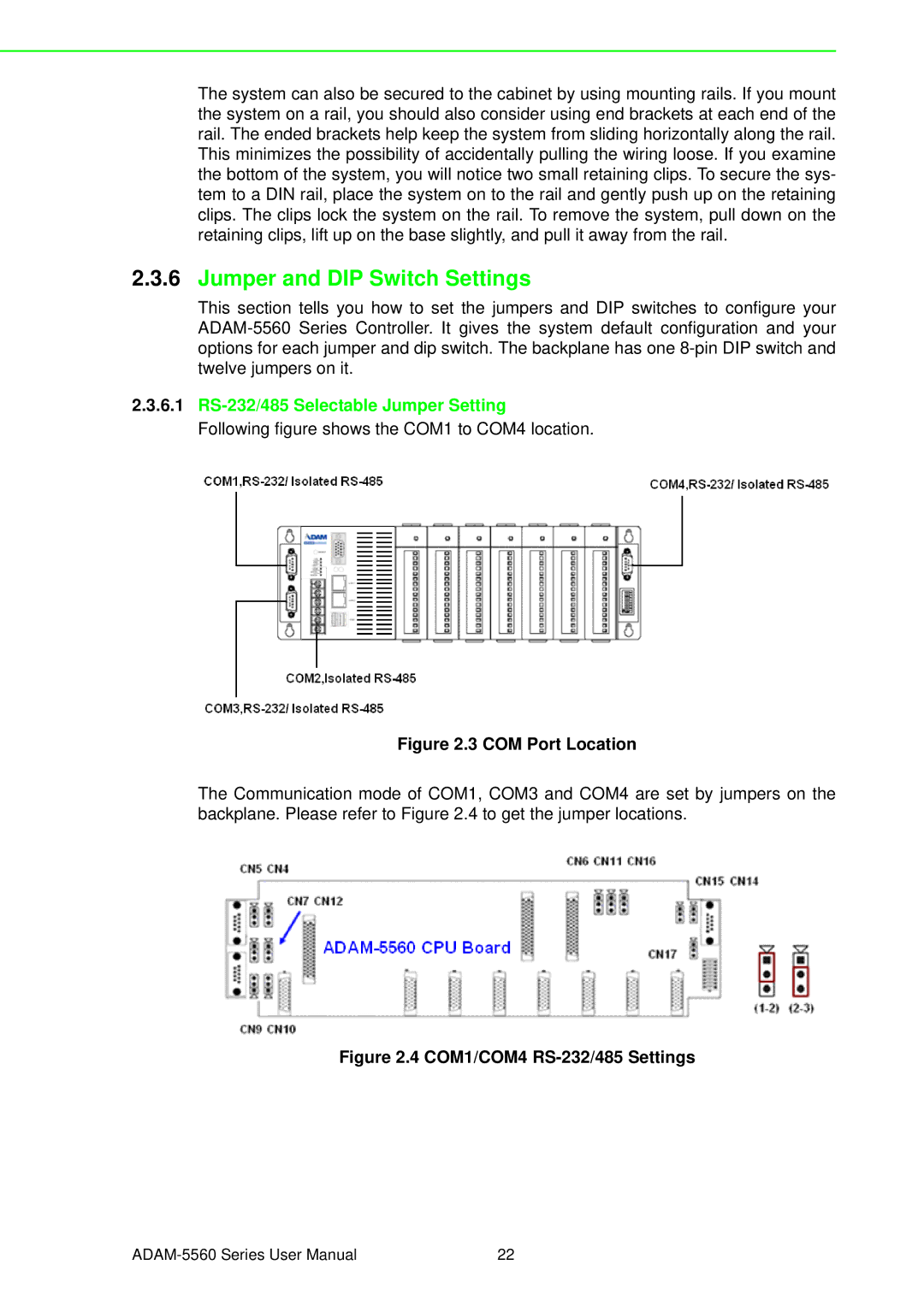
Following figure shows the COM1 to COM4 location.
Figure 2.3 COM Port Location
The Communication mode of COM1, COM3 and COM4 are set by jumpers on the backplane. Please refer to Figure 2.4 to get the jumper locations.
Figure 2.4 COM1/COM4 RS-232/485 Settings
22 |