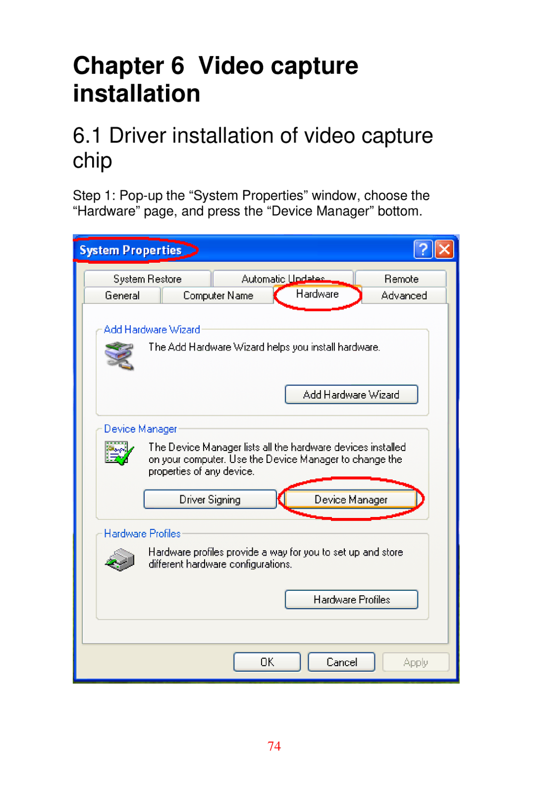
Manuals
/
Brands
/
Computer Equipment
/
Computer Hardware
/
Advantech
/
Computer Equipment
/
Computer Hardware
Advantech
DVMB-554E
- page 74
1
74
94
94
Download
94 pages, 1.76 Mb
74
Chapter 6 Video capture
installation
6.1 Driver installation of video capture
chip
Step 1: Pop-up the “System Pr
operties” window, choose the
“Hardware” page, and press t
he “Device Manager” bottom.
Contents
Main
DVMB-554E
User Manual
Page
Page
Page
Page
Page
Page
Page
Page
Page
Page
General Information
Chapter 1 Hardware Configuration
1.2 Features
1.3.1 System
1.3.2 Memory
1.3.4 Graphics
1.3.3 Input/Output
1.3.5 Ethernet LAN
1.3.7 Mechanical and environmental specifications
1.3.6 Industrial features
1.4 Jumpers and Connectors
Page
1.5 Board Layout: Jumper and Connector Locations
1.6 DVMB-554E Block Diagram
1.7 Safety Precautions
1.8 Jumper Settings
1.8.1 How to set jumpers
1.8.2 CMOS clear (J3)
1.8.3 Watchdog timer output (J4)
1.8.4 COM2 RS 232/422/485 mode selector (J2)
1.8.5 LVDS Power 3.3V/5V selector (J6)
1.9 System Memory
1.12 Processor Installation
Page
Chapter 2 Connecting Peripherals
2.4 VGA and DVI connector module (V1)
2.5 Serial port module: COM1/COM2 (CM1)
2.7 Fan Connector (FN1/FN2/FN3)
2.8 Front Panel Connectors (CNX1/CN13)
Keyboard Lock (CN13)
External Speaker (CNX1-17)
2.8.3
Reset Connector (CNX1-18)
SM Bus Connector (CNX1-29)
2.8.6
2.9 H/W Monitor Alarm (CN12)
2.11 Aux Line-In Connector (CN7)
2.13 DVA-210 Connector (VDO1)
Page
2.16 LVDS connector (VCN1)
2.17 LCD Inverter Power connector (BKL1)
Page
Chapter 3 Award BIOS Setup
3.1.1 CMOS RAM Auto-backup and Restore
3.2 Entering Setup
3.3.1 Date
3.3.3 IDE channel 0/1 Master/Slave
3.3.2 Time
3.3.4 Halt
On
3.3.5 Memory
3.4 Advanced BIOS Features
3.4.1 CPU Features
Other Device
3.4.7 Boot
3.4.8
Status
Mode
3.4.14 APIC
3.4.15
For OS
MPS Version Control
3.5.1 DRAM Timing Selectable
3.5.3 DRAM RAS# to CAS# Delay
3.5.2 CAS Latency Time
3.5.4 DRAM RAS# Precharge
PCI-Express Root Port Func
3.5.10
Page
Init Display First
3.5.17
3.6.1 IDE HDD Block Mode
3.6.4 SATA Mode
IDE Device
3.6.5 On-Chip Serial
ATA
3.6.8 USB Controller
3.6.7 SATA Port
Mode
Page
Page
3.7 Power Management Setup
3.7.1 PCI Express PM Function
3.7.5 Video Off In Suspend
3.7.2 ACPI Function
3.7.6 Suspend Type
IDE 0 (1)
Primary IDE 0 (1) and Secondary
3.7.16
FDD, COM, LPT PORT
PWRON After PWR-Fail
3.7.18
3.8 PnP/PCI Configurations
3.8.1 Reset Configuration Data
3.8.4 Maximum Payload Size
3.8.3 PCI / VGA Palette Snoop
3.8.2 Resources Controlled By
3.9 PC Health Status
3.9.1 CPU Warning Temperature
3.9.7 Shutdown Temperature
3.9.6 VCORE and Other Voltages
2 Speed
3.10 Frequency / Voltage Control
Spectrum
3.10.1 Spread
Page
Chapter 4 Chipset Installation
Page
Page
Page
Page
Chapter 5 VGA Setup
Page
Page
Page
Page
Page
Page
Page
Page
Page
Page
Page
Page
Page
Page
Page
6.3 Demo Program Functionality
6.3.1 Device
Page
6.3.3 Resolution
Page
Page
Page
Page
6.3.8 Sensor Control
6.3.9 Micro Control
6.3.10 GPIO control