3 - Troubleshooting
E221 | Front Panel comm UART framing error | A3 Front Panel/Display Bd |
E222 | Front Panel comm UART parity error | A3 Front Panel/Display Bd |
E223 | Front Panel firmware input buffer overrun | A3 Front Panel/Display Bd |
CV/CC Status Annunciators Troubleshooting
The CV/CC annunciators are particularly helpful when troubleshooting a unit with no output voltage or current. If the unit has passed self test the programming DAC circuits on the A2 circuit board are probably working properly. If either the CV or CC annunciators is on then the problem is in either the CV or CC control circuits located on the A1 Main board. If UNR is indicated then neither the voltage nor the current circuits are in control and the problem would be in the main power transformer or the driver or output regulator stages circuits, also on A1 but after the gating diodes.
Bias and Reference Supplies
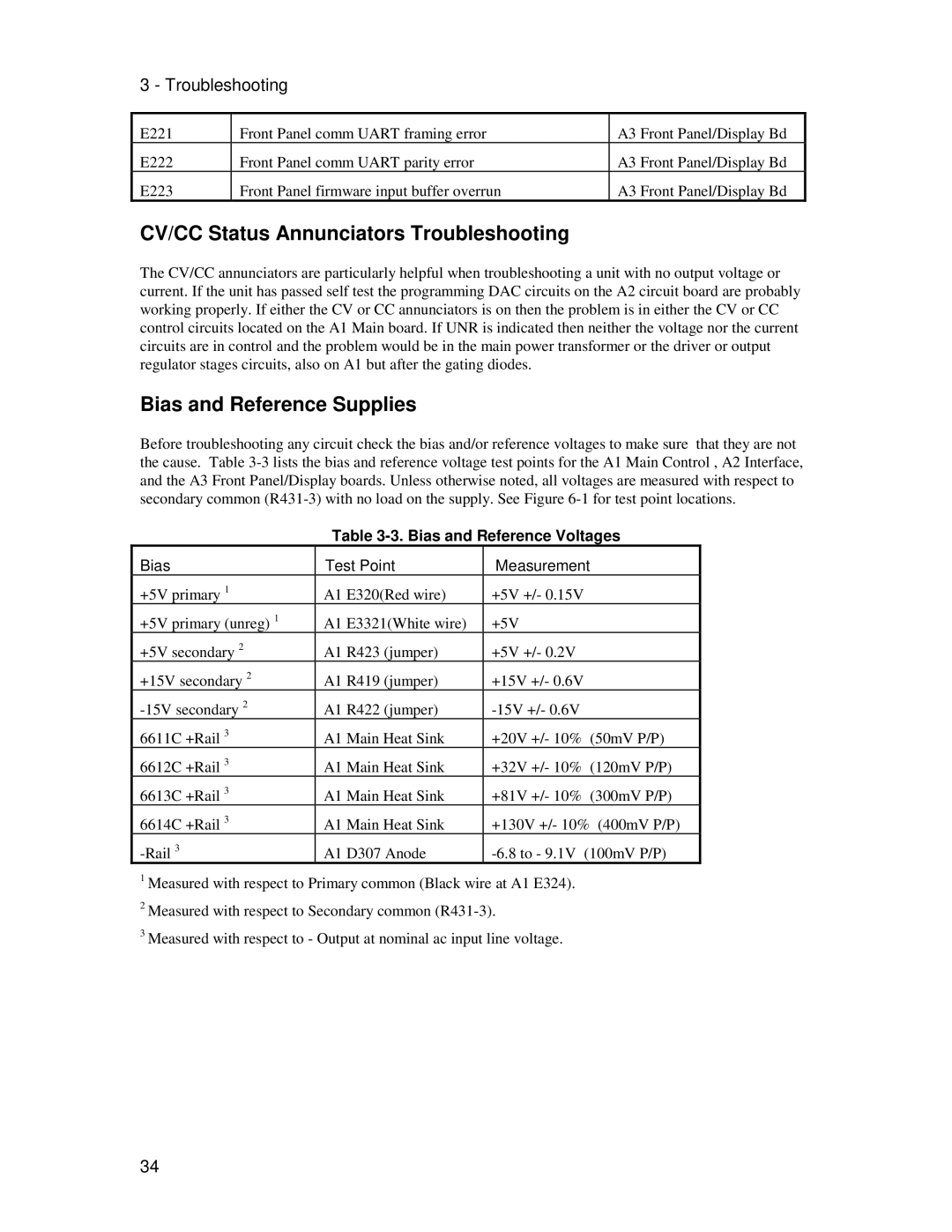
Before troubleshooting any circuit check the bias and/or reference voltages to make sure that they are not the cause. Table
Table 3-3. Bias and Reference Voltages
Bias | Test Point | Measurement | |||
+5V primary 1 | A1 | E320(Red wire) | +5V | +/- 0.15V | |
+5V primary (unreg) 1 | A1 | E3321(White wire) | +5V |
|
|
+5V secondary 2 | A1 | R423 (jumper) | +5V | +/- 0.2V | |
+15V secondary 2 | A1 | R419 (jumper) | +15V +/- 0.6V | ||
A1 | R422 (jumper) | ||||
6611C +Rail 3 | A1 | Main Heat Sink | +20V | +/- 10% (50mV P/P) | |
6612C +Rail 3 | A1 | Main Heat Sink | +32V | +/- 10% (120mV P/P) | |
6613C +Rail 3 | A1 | Main Heat Sink | +81V | +/- 10% (300mV P/P) | |
6614C +Rail 3 | A1 | Main Heat Sink | +130V +/- 10% (400mV P/P) | ||
A1 | D307 Anode | ||||
1Measured with respect to Primary common (Black wire at A1 E324).
2Measured with respect to Secondary common
3Measured with respect to - Output at nominal ac input line voltage.
34
