Manuals
/
Agilent Technologies
/
Video Game
/
Video Gaming Accessories
Agilent Technologies
5962-8200
service manual
A2/A3 Boards Block Diagram
Models:
5962-8200
1
55
58
58
Download
58 pages
2.56 Kb
51
52
53
54
55
56
57
58
Troubleshooting
Parts list
Error codes
Flow Charts
Interface Signals
Password
Safety Symbol Definitions
Line Voltage Wiring
Warranty
Cover, Removal and Replacement
Page 55
Image 55
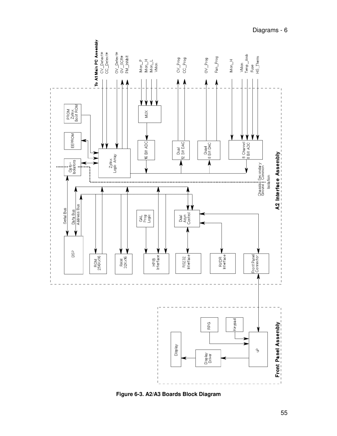
Diagrams - 6
Figure
6-3.
A2/A3 Boards Block Diagram
55
Page 54
Page 56
Page 55
Image 55
Page 54
Page 56
Contents
Agilent Part No Microfiche No September
Certification
Warranty Information
Before Applying Power
Safety Summary
Symbol Description
Safety Symbol Definitions
Instrument Identification
Printing History
Table of Contents
Introduction
Initialization ROM Upgrade
Disassembly Procedures
Post-repair Calibration
Page
Chapter
Safety Considerations
Organization
Related Documents
Firmware Revisions
Revisions
Electrostatic Discharge
Manual Revisions
Test Equipment Required
Introduction
Type Specifications Recommended Model
Test Setup
Measurement Techniques
Electronic Load
Test Setup
Programming
Operation Verification Tests
Performance Tests
Current-Monitoring Resistor
CV Load Effect
CV Setup
Constant Voltage CV Tests
Voltage Programming and Readback Accuracy
CV Source Effect
Transient Recovery Time
CV Noise Pard
Constant Current CC Tests
CC Setup
Current Programming and Readback Accuracy
Low Range Current Readback Accuracy
Current Sink -CC Operation
CC Load Effect
CC Load and Line Regulation
CC Noise Pard
CC Source Effect
Performance Test Equipment Form
Current Sink @ -3A Readback MA Range Current Readback
Load Effect Source Effect Pard Ripple and Noise
Transient Response
Constant Current Tests Current Programming and Readback
Iout −
Vout −
Load Effect Vout − Vout + 2.0mV
Source Effect Vout −
Current Sink @ -0.6A Readback Iout −
Vout + 4 mV
Iout − Iout + 0.2 mA
Iout − Iout + 2.2 mA
Current Sink @ -0.3A Readback Iout −
Load Effect Vout − Vout + 5 mV
Iout − Iout + 0.1 mA
Iout − Iout + 1.1 mA
Page
Troubleshooting
Type Purpose Recommended Model
Overall Troubleshooting
Flow Charts
Test Equipment Required for Troubleshooting
Sheet 1. Troubleshooting Flowchart
Sheet 2. Troubleshooting Flowchart
Sheet 3. Troubleshooting Flowchart
Sheet 4. Troubleshooting Flowchart
Error Code Description Probable Cause
Specific Troubleshooting Procedures
Power-on Self-test Failures
Self-Test Error Codes/Messages
Bias Test Point Measurement
CV/CC Status Annunciators Troubleshooting
Bias and Reference Supplies
Bias and Reference Voltages
Voltage Measurements at J207 A2 Interface to A1 Main board
J307 Voltage Measurements
Manual Fan Speed Control
Disabling Protection Features
Calibration Password
Inhibit Calibration Switch
Post-repair Calibration
Identifying the Firmware
ROM Upgrade
Upgrade Procedure
Initialization
List of Required Tools
Disassembly Procedures
A2 Interface Board, Removal and Replacement
Cover, Removal and Replacement
Front Panel Assembly, Removal and Replacement
T1 Power Transformer, Removal and Replacement
A3 Front Panel Board, Removal and Replacement
A1 Main Control Board
Line Voltage Wiring
Power Supply Interface signals
Interface Signals
Connector Signal Description
Secondary Interface
A3 Front Panel Circuits
A2 Interface Circuits
Primary Interface
A1 Main Board Circuits
Power Circuits
Control Circuits
Principles of Operation
Page
Designator PartNumber Qty Description
Chassis, Electrical
Replaceable Parts List
Mechanical Parts Identification
MP9
Chassis, Mechanical
Diagrams
Diagrams
A2/A3 Boards Block Diagram
Circuits
Bias
Index
Index
Top
Page
Image
Contents