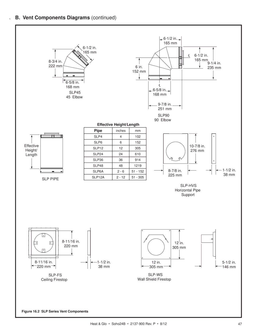
B. Vent Components Diagrams (continued)
222 mm
| ||
165 mm | ||
| ||
165 mm | ||
| ||
6 in. | 165 | |
235 mm | ||
152 mm |
| |
| ||
168 mm | ||
SLP45 | ||
168 mm | ||
45° Elbow | ||
|
251 mm
SLP90
90° Elbow
Effective Height/Length
Effective
Height/
Length
SLP PIPE
Pipe | inches | mm |
SLP4 | 4 | 102 |
|
|
|
SLP6 | 6 | 152 |
SLP12 | 12 | 305 |
SLP24 | 24 | 610 |
|
|
|
SLP36 | 36 | 914 |
SLP48 | 48 | 1219 |
|
|
|
SLP6A | 2 - 6 | 51 - 152 |
SLP12A | 2 - 12 | 51 - 305 |
|
|
|
276 mm
225 mm
![]()
Horizontal Pipe
Support
220 mm
![]() 220 mm
220 mm ![]()
Ceiling Firestop
12 in.
305 mm
|
|
|
| 12 in. | ||
38 mm |
|
|
|
| 305 mm |
|
|
| |||||
|
| |||||
Wall Shield Firestop
![]() 146 mm
146 mm
Figure 16.2 SLP Series Vent Components
Heat & Glo • Soho24B • | 47 |