5 Vent Information and Diagrams
A. Vent Table Key
The abbreviations listed in this vent table key are used in the vent diagrams.
Symbol | Description |
|
|
V1 | First section (closest to appliance) of vertical length |
|
|
V2 | Second section of vertical length |
|
|
H1 | First section (closest to appliance) of horizontal length |
|
|
H2 | Second section of horizontal length |
|
|
![]() WARNING
WARNING
Fire Hazard. Explosion Risk. Asphyxiation Risk.
Do NOT connect this gas appliance to a chimney flue serving a separate
• Vent this appliance directly outside.
• Use separate vent system for this appliance.
May impair safe operation of this appliance or other appliances connected to the flue.
B. Use of Elbows
CAUTION
ALL vent configuration specifications MUST be followed.
•This product is tested and listed to these specifications.
•Appliance performance will suffer if specifications are not followed.
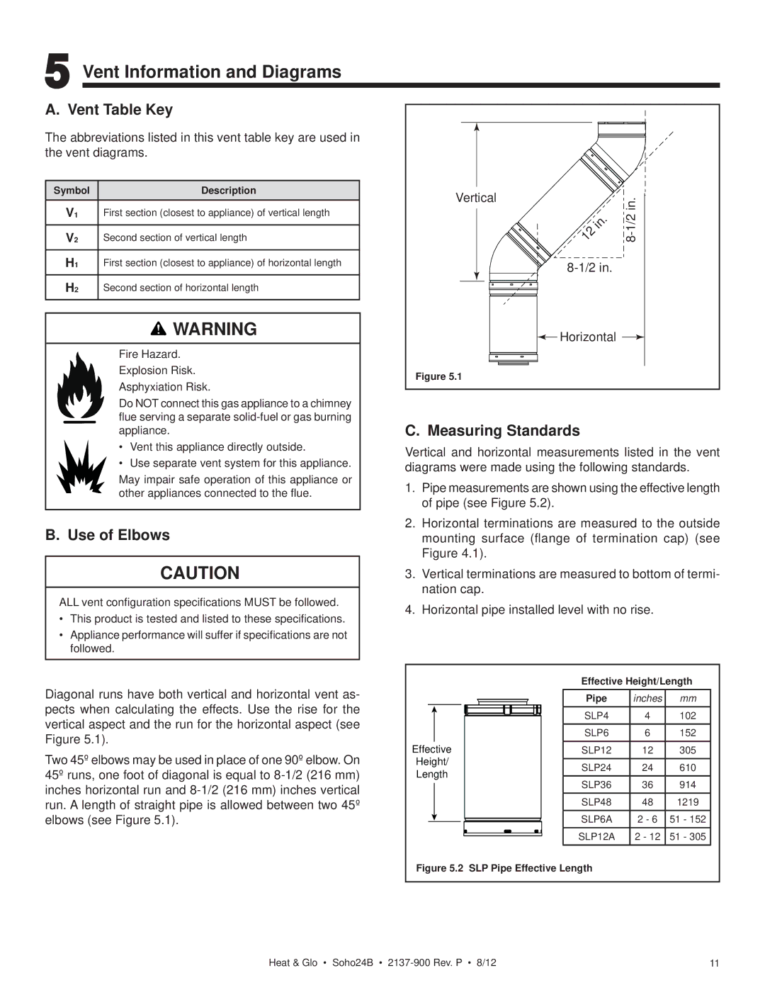
Diagonal runs have both vertical and horizontal vent as- pects when calculating the effects. Use the rise for the vertical aspect and the run for the horizontal aspect (see Figure 5.1).
Two 45º elbows may be used in place of one 90º elbow. On 45º runs, one foot of diagonal is equal to
Verticalin.
 Horizontal
Figure 5.1
C. Measuring Standards
Vertical and horizontal measurements listed in the vent diagrams were made using the following standards.
1.Pipe measurements are shown using the effective length of pipe (see Figure 5.2).
2.Horizontal terminations are measured to the outside mounting surface (flange of termination cap) (see Figure 4.1).
3.Vertical terminations are measured to bottom of termi- nation cap.
4.Horizontal pipe installed level with no rise.
| Effective Height/Length | |||
| Pipe | inches | mm | |
| SLP4 | 4 | 102 | |
| SLP6 | 6 | 152 | |
Effective | SLP12 | 12 | 305 | |
Height/ | SLP24 | 24 | 610 | |
Length | ||||
SLP36 | 36 | 914 | ||
| ||||
| SLP48 | 48 | 1219 | |
| SLP6A | 2 - 6 | 51 - 152 | |
| SLP12A | 2 - 12 | 51 - 305 | |
Figure 5.2 SLP Pipe Effective Length
Heat & Glo • Soho24B • | 11 |