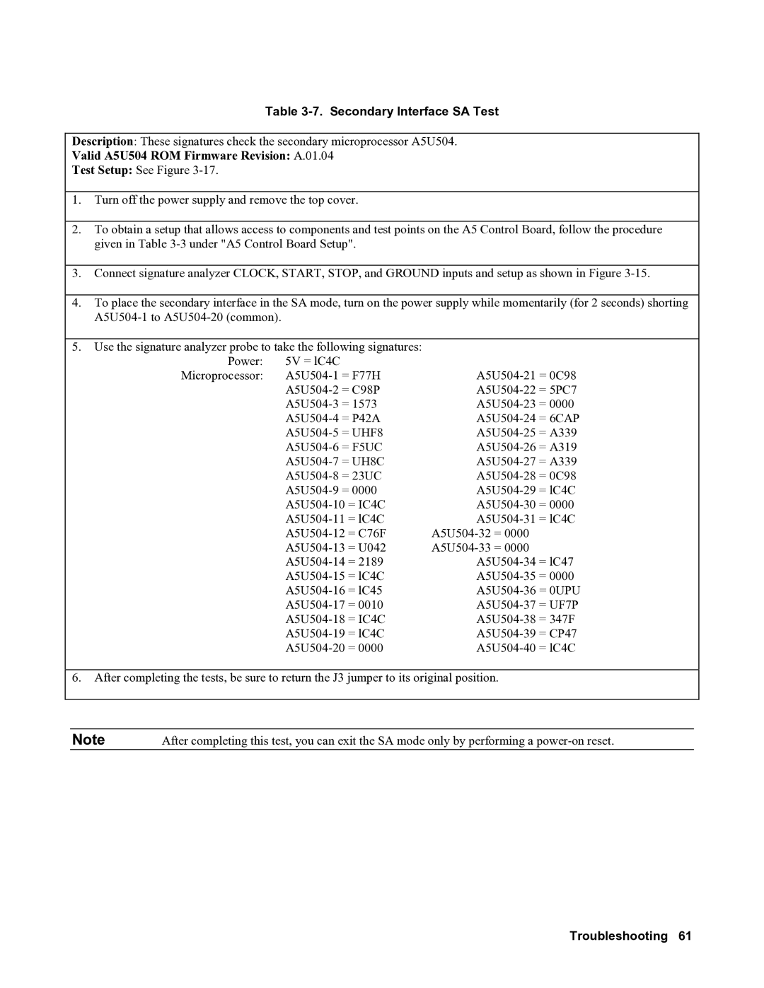
Table 3-7. Secondary Interface SA Test
Description: These signatures check the secondary microprocessor A5U504.
Valid A5U504 ROM Firmware Revision: A.01.04
Test Setup: See Figure
1.Turn off the power supply and remove the top cover.
2.To obtain a setup that allows access to components and test points on the A5 Control Board, follow the procedure given in Table
3.Connect signature analyzer CLOCK, START, STOP, and GROUND inputs and setup as shown in Figure
4.To place the secondary interface in the SA mode, turn on the power supply while momentarily (for 2 seconds) shorting
5.Use the signature analyzer probe to take the following signatures:
Power: | 5V = lC4C |
|
Microprocessor: | ||
| ||
| ||
| ||
| ||
| ||
| ||
| ||
| ||
| ||
| ||
| ||
| ||
| ||
| ||
| ||
| ||
| ||
| ||
|
6.After completing the tests, be sure to return the J3 jumper to its original position.
Note | After completing this test, you can exit the SA mode only by performing a |
