Table 2-4. Constant Voltage (CV) Tests (continued)
| Action | Normal Result |
|
|
|
Transient Recovery Time
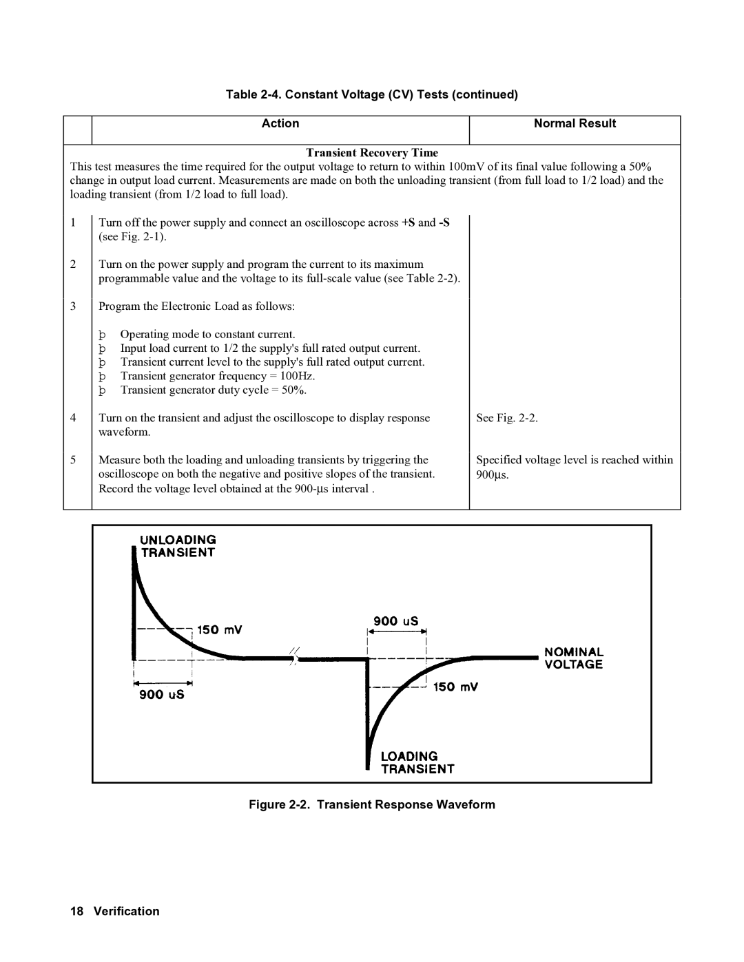
This test measures the time required for the output voltage to return to within 100mV of its final value following a 50% change in output load current. Measurements are made on both the unloading transient (from full load to 1/2 load) and the loading transient (from 1/2 load to full load).
1
2
3
4
5
Turn off the power supply and connect an oscilloscope across +S and
Turn on the power supply and program the current to its maximum programmable value and the voltage to its
Program the Electronic Load as follows:
þOperating mode to constant current.
þInput load current to 1/2 the supply's full rated output current.
þTransient current level to the supply's full rated output current.
þTransient generator frequency = 100Hz.
þTransient generator duty cycle = 50%.
Turn on the transient and adjust the oscilloscope to display response waveform.
Measure both the loading and unloading transients by triggering the oscilloscope on both the negative and positive slopes of the transient. Record the voltage level obtained at the
See Fig.
Specified voltage level is reached within 900∝s.