2010 | IF Err THEN |
|
2020 | PRINT "An error occurred during the EEPROM read/write, Check for" | |
2030 | PRINT "programming errors. Initialization data may be incorrect." | |
2040 | STOP |
|
2050 | END IF |
|
2060 | ! |
|
2070 | PRINT "Operation complete. Program stopped." |
|
2080 | STOP |
|
2090 | ! |
|
2100 | Ps_error: | ! Error handling subroutine |
2110 | OUTPUT @Ps;"SYST:ERR?" | ! Check for errors |
2120 | ENTER @Ps;Err |
|
2130 | RETURN |
|
2140 | ! |
|
2150 | END |
|
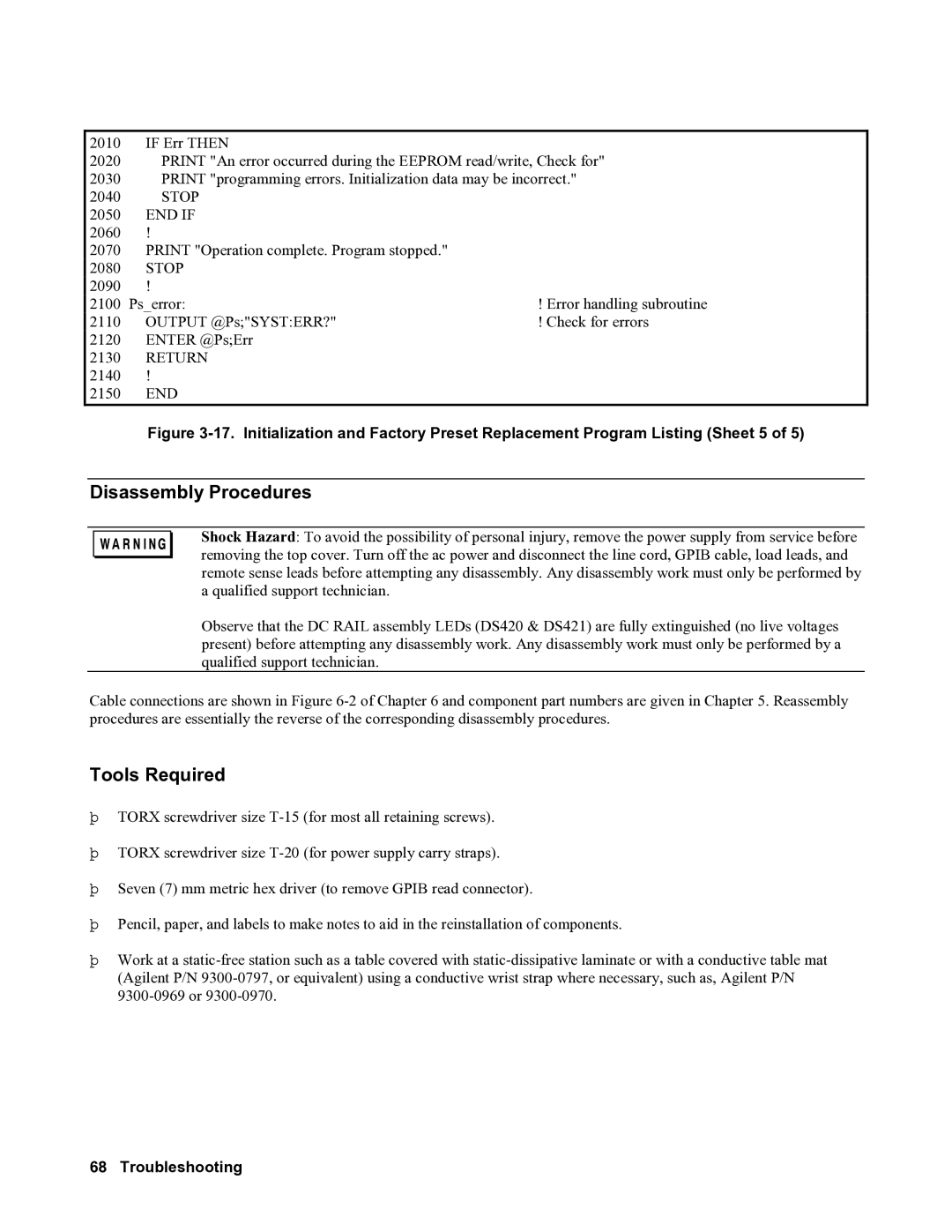
Figure 3-17. Initialization and Factory Preset Replacement Program Listing (Sheet 5 of 5)
Disassembly Procedures
Shock Hazard: To avoid the possibility of personal injury, remove the power supply from service before removing the top cover. Turn off the ac power and disconnect the line cord, GPIB cable, load leads, and remote sense leads before attempting any disassembly. Any disassembly work must only be performed by a qualified support technician.
Observe that the DC RAIL assembly LEDs (DS420 & DS421) are fully extinguished (no live voltages present) before attempting any disassembly work. Any disassembly work must only be performed by a qualified support technician.
Cable connections are shown in Figure
Tools Required
þTORX screwdriver size
þTORX screwdriver size
þSeven (7) mm metric hex driver (to remove GPIB read connector).
þPencil, paper, and labels to make notes to aid in the reinstallation of components.
þWork at a