6
Diagrams
Introduction
This chapter contains drawings and diagrams for troubleshooting and maintaining Agilent Series 668xA Power Supplies. Unless otherwise specified, a drawing or diagram applies to all models of the series. Wiring connections to external equipment are shown in the Power Supply Operating Manual.
Chapter Organization
Table
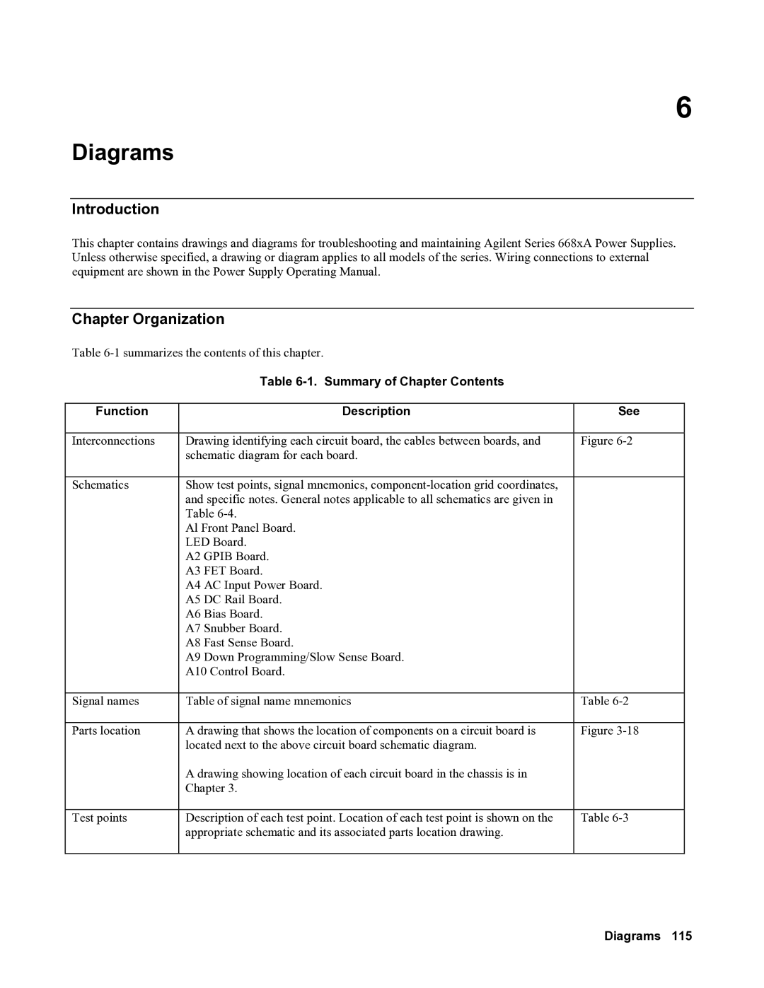
Table 6-1. Summary of Chapter Contents
Function |
| Description | See |
|
|
| |
Interconnections | Drawing identifying each circuit board, the cables between boards, and | Figure | |
| schematic diagram for each board. |
| |
|
|
| |
Schematics | Show test points, signal mnemonics, |
| |
| and specific notes. General notes applicable to all schematics are given in |
| |
| Table |
| |
| Al Front Panel Board. |
| |
| LED Board. |
| |
| A2 | GPIB Board. |
|
| A3 | FET Board. |
|
| A4 AC Input Power Board. |
| |
| A5 | DC Rail Board. |
|
| A6 | Bias Board. |
|
| A7 | Snubber Board. |
|
| A8 | Fast Sense Board. |
|
| A9 | Down Programming/Slow Sense Board. |
|
| A10 Control Board. |
| |
|
|
| |
Signal names | Table of signal name mnemonics | Table | |
|
|
| |
Parts location | A drawing that shows the location of components on a circuit board is | Figure | |
| located next to the above circuit board schematic diagram. |
| |
| A drawing showing location of each circuit board in the chassis is in |
| |
| Chapter 3. |
| |
|
|
| |
Test points | Description of each test point. Location of each test point is shown on the | Table | |
| appropriate schematic and its associated parts location drawing. |
| |
|
|
|
|