Getting Started | ESG Family Signal Generators |
The Signal Generator at a Glance |
|
The Signal Generator at a Glance
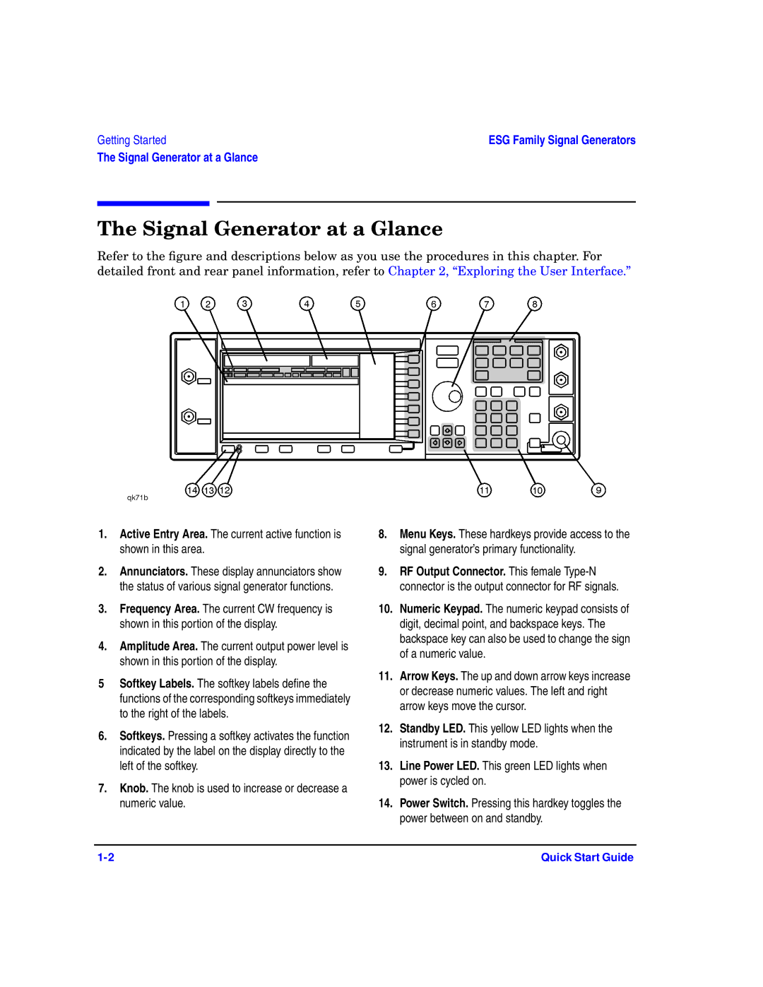
Refer to the figure and descriptions below as you use the procedures in this chapter. For detailed front and rear panel information, refer to Chapter 2, “Exploring the User Interface.”
1.Active Entry Area. The current active function is shown in this area.
2.Annunciators. These display annunciators show the status of various signal generator functions.
3.Frequency Area. The current CW frequency is shown in this portion of the display.
4.Amplitude Area. The current output power level is shown in this portion of the display.
5Softkey Labels. The softkey labels define the functions of the corresponding softkeys immediately to the right of the labels.
6.Softkeys. Pressing a softkey activates the function indicated by the label on the display directly to the left of the softkey.
7.Knob. The knob is used to increase or decrease a numeric value.
8.Menu Keys. These hardkeys provide access to the signal generator’s primary functionality.
9.RF Output Connector. This female
10.Numeric Keypad. The numeric keypad consists of digit, decimal point, and backspace keys. The backspace key can also be used to change the sign of a numeric value.
11.Arrow Keys. The up and down arrow keys increase or decrease numeric values. The left and right arrow keys move the cursor.
12.Standby LED. This yellow LED lights when the instrument is in standby mode.
13.Line Power LED. This green LED lights when power is cycled on.
14.Power Switch. Pressing this hardkey toggles the power between on and standby.
Quick Start Guide |