ASSEMBLY
OPTIONAL A-FRAME ASSEMBLY
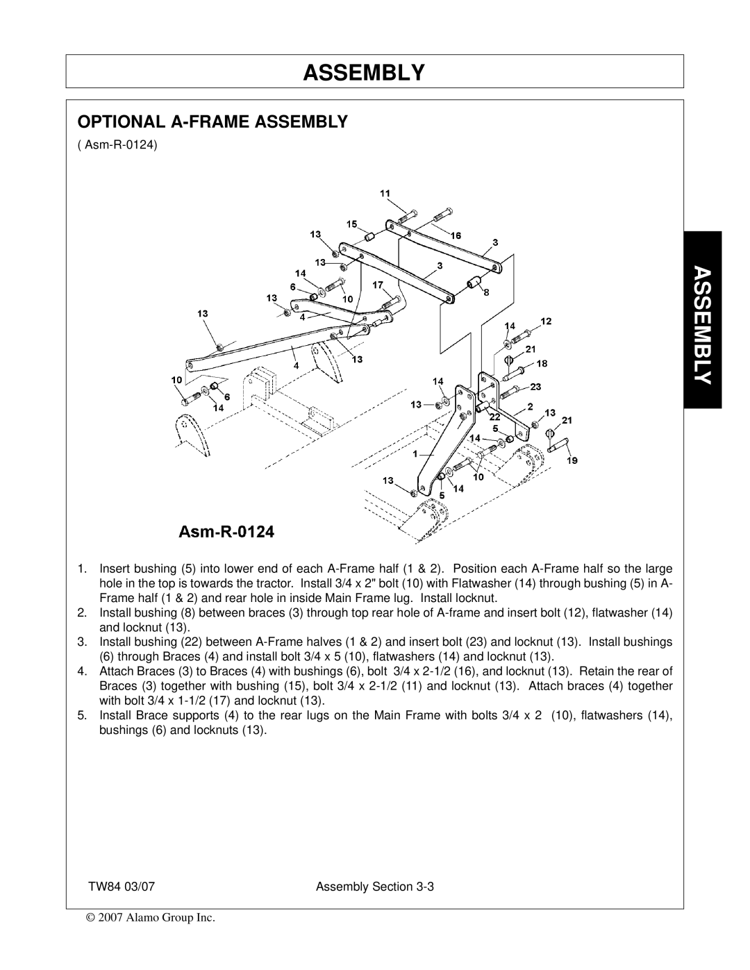
( Asm-R-0124)
1.Insert bushing (5) into lower end of each A-Frame half (1 & 2). Position each A-Frame half so the large hole in the top is towards the tractor. Install 3/4 x 2" bolt (10) with Flatwasher (14) through bushing (5) in A- Frame half (1 & 2) and rear hole in inside Main Frame lug. Install locknut.
2.Install bushing (8) between braces (3) through top rear hole of A-frame and insert bolt (12), flatwasher (14) and locknut (13).
3.Install bushing (22) between A-Frame halves (1 & 2) and insert bolt (23) and locknut (13). Install bushings
(6) through Braces (4) and install bolt 3/4 x 5 (10), flatwashers (14) and locknut (13).
4.Attach Braces (3) to Braces (4) with bushings (6), bolt 3/4 x 2-1/2 (16), and locknut (13). Retain the rear of Braces (3) together with bushing (15), bolt 3/4 x 2-1/2 (11) and locknut (13). Attach braces (4) together with bolt 3/4 x 1-1/2 (17) and locknut (13).
5.Install Brace supports (4) to the rear lugs on the Main Frame with bolts 3/4 x 2 (10), flatwashers (14), bushings (6) and locknuts (13).
TW84 03/07 | Assembly Section 3-3 |
© 2007 Alamo Group Inc.