3
2
1
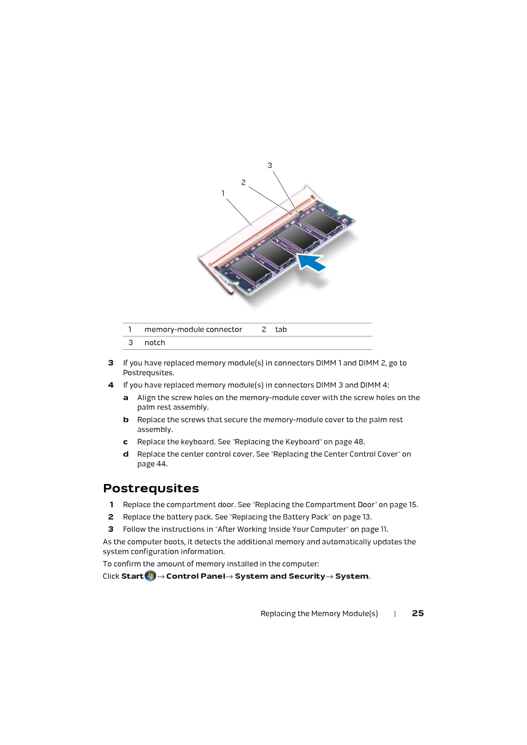
1 | 2 tab | |
|
|
|
3 | notch |
|
|
|
|
3If you have replaced memory module(s) in connectors DIMM 1 and DIMM 2, go to Postrequsites.
4If you have replaced memory module(s) in connectors DIMM 3 and DIMM 4:
a Align the screw holes on the
b Replace the screws that secure the
c Replace the keyboard. See "Replacing the Keyboard" on page 48.
d Replace the center control cover. See "Replacing the Center Control Cover" on page 44.
Postrequsites
1Replace the compartment door. See "Replacing the Compartment Door" on page 15.
2Replace the battery pack. See "Replacing the Battery Pack" on page 13.
3Follow the instructions in "After Working Inside Your Computer" on page 11.
As the computer boots, it detects the additional memory and automatically updates the system configuration information.
To confirm the amount of memory installed in the computer:
Click Start → Control Panel→ System and Security→ System.
Replacing the Memory Module(s) | 25 |