11 | Removing the Memory |
Module(s) |
WARNING: Before working inside your computer, read the safety information that shipped with your computer and follow the steps in "Before You Begin" on page 9. For additional safety best practices information, see the Regulatory Compliance Homepage at dell.com/ regulatory_compliance.
NOTE: Your computer supports up to four memory module connectors. You can access connectors DIMM 1 and DIMM 2 by removing the compartment door at the bottom of your computer. You can access connectors DIMM 3 and DIMM 4 by removing the
Prerequsites
1Remove the battery pack. See "Removing the Battery Pack" on page 12.
2Remove the compartment door. See "Removing the Compartment Door" on page 14.
Procedure
1To remove memory module(s) from connectors DIMM 1 and DIMM 2, go to step 3.
2To remove
a Remove the center control cover. See "Removing the Center Control Cover" on page 41.
b Remove the keyboard. See "Removing the Keyboard" on page 45.
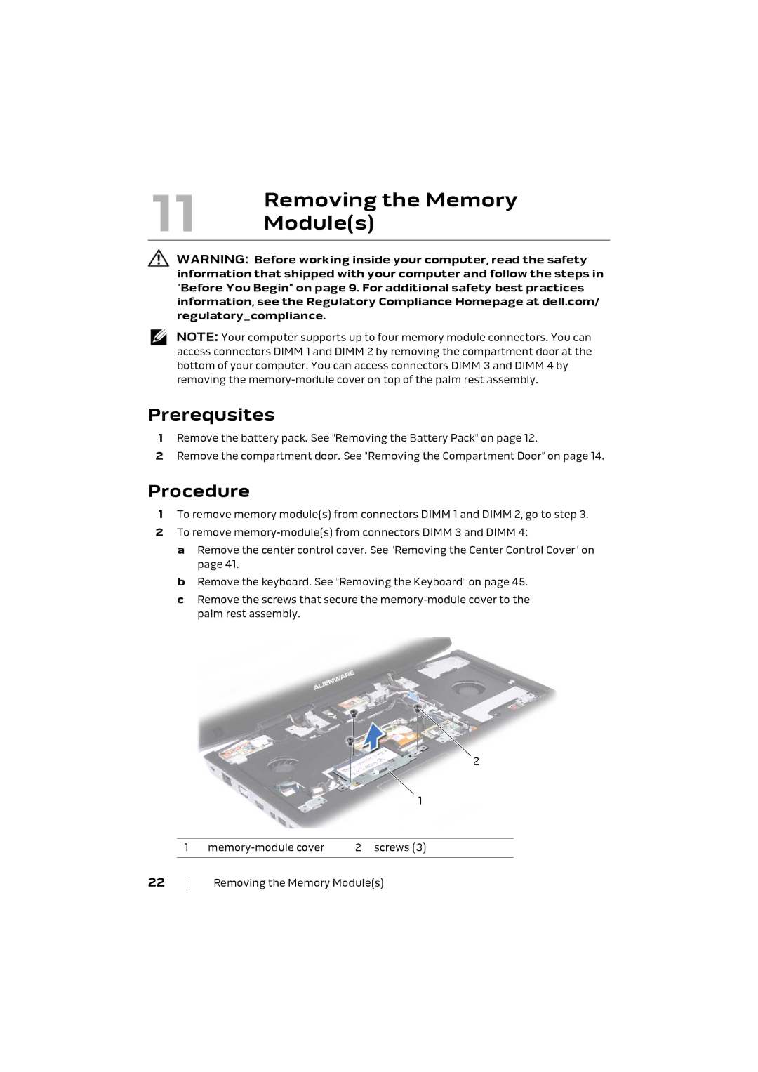
c Remove the screws that secure the
2
|
|
| 1 |
|
|
|
|
| 1 | 2 screws (3) | |
22 |
|
| |
Removing the Memory Module(s) | |||