Connect Power and Ground | Installing Power and Ground for the 9102 |
|
|
1.9 Installing Power and Ground for the 9102
1.9.1 Connect Power and Ground
The Allied Telesyn 9102 comes with a
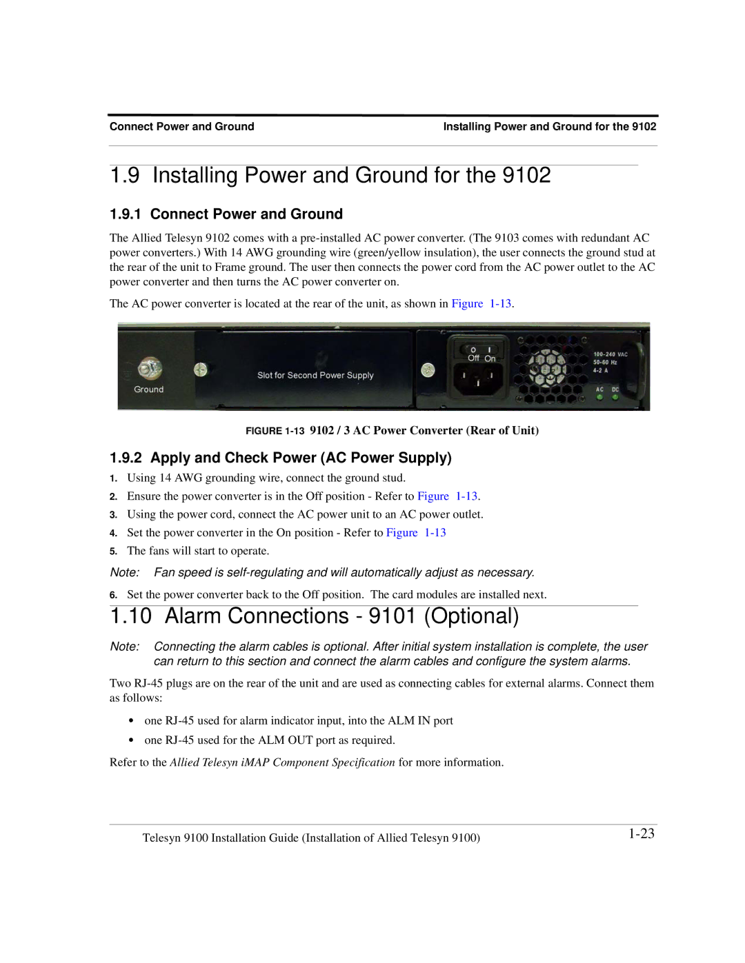
The AC power converter is located at the rear of the unit, as shown in Figure
FIGURE 1-13 9102 / 3 AC Power Converter (Rear of Unit)
1.9.2 Apply and Check Power (AC Power Supply)
1.Using 14 AWG grounding wire, connect the ground stud.
2.Ensure the power converter is in the Off position - Refer to Figure
3.Using the power cord, connect the AC power unit to an AC power outlet.
4.Set the power converter in the On position - Refer to Figure
5.The fans will start to operate.
Note: Fan speed is
6.Set the power converter back to the Off position. The card modules are installed next.
1.10 Alarm Connections - 9101 (Optional)
Note: Connecting the alarm cables is optional. After initial system installation is complete, the user can return to this section and connect the alarm cables and configure the system alarms.
Two
•one
•one
Refer to the Allied Telesyn iMAP Component Specification for more information.
Telesyn 9100 Installation Guide (Installation of Allied Telesyn 9100) |