Descriptions
The following sections describe the
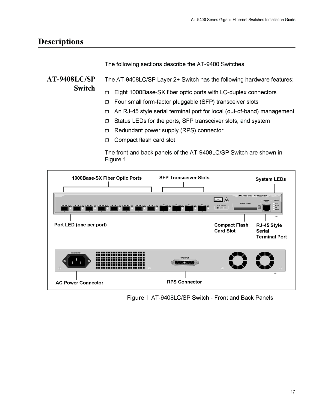
AT-9408LC/SP Switch
The
Eight
Four small
An
Status LEDs for the ports, SFP transceiver slots, and system
Redundant power supply (RPS) connector
Compact flash card slot
The front and back panels of the
SFP Transceiver Slots | System LEDs | |||||
|
|
|
|
|
|
|
|
|
|
|
|
|
|
1 |
L/A | L/A |
| 2 |
3 |
L/A | L/A |
| 4 |
5 |
L/A | L/A |
| 6 |
L/A |
7 |
CLASS 1
LASER PRODUCT
SFP | SFP | SFP | SFP |
L/A | L/A | L/A | L/A | L/A | PORT ACTIVITY | ||
|
|
|
|
| L/A | LINK / | ACT |
8 | 9 | 10 | 11 | 12 |
|
|
|
|
|
|
| TERMINAL | STATUS |
|
|
|
| PORT |
|
| COMPACT FLASH | FAULT | |||
|
| EJECT | MASTER | ||
|
|
|
|
| RPS |
|
|
|
|
| POWER |
|
|
|
|
| 461 |
|
|
|
|
|
|
|
|
Port LED (one per port) | Compact Flash | |||||
|
| Card Slot | Serial | |||
|
|
|
| Terminal Port | ||
RPS INPUT
462
AC Power Connector | RPS Connector |
Figure 1 AT-9408LC/SP Switch - Front and Back Panels
17