Chapter 1: Overview
AT-9424T/GB Switch
The
24
Two gigabit interface connector (GBIC) transceiver slots
An
Status LEDs for the ports, transceiver slots, and system
Redundant power supply connector
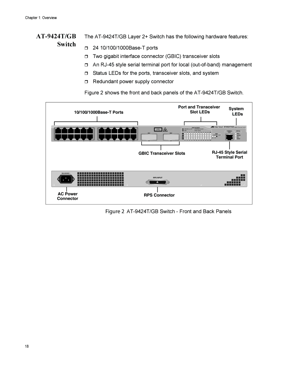
Figure 2 shows the front and back panels of the AT-9424T/GB Switch.
| Port and Transceiver | System | |
Slot LEDs | |||
LEDs | |||
|
|
1 | 3 | 5 | 7 | 9 | 11 |
| 13 | 15 | 17 | 19 | 21 | 23R |
|
|
|
|
|
|
|
|
|
|
|
|
|
2 | 4 | 6 | 8 | 10 | 12 |
| 14 | 16 | 18 | 20 | 22 | 24R |
CLASS 1
LASER PRODUCT
GBIC |
23 |
|
|
|
| PORT ACTIVITY |
|
|
|
|
| |||||
L/A | 1000 LINK / |
| ACT |
| 10/100 LINK / |
| ACT |
|
|
|
|
| ||
D/C | FDX |
|
|
|
| HDX / | COL |
|
|
|
| TERMINAL | STATUS | |
| 1 | 3 | 5 | 7 | 9 | 11 | 13 | 15 | 17 | 19 | 21 | 23R | PORT |
|
GBIC | L/A |
|
|
|
|
|
|
|
|
|
|
| GBIC |
| FAULT |
|
|
|
|
|
|
|
|
|
|
|
|
| |||
| D/C |
|
|
|
|
|
|
|
|
|
|
| 1000 LINK / | ACT | MASTER |
| L/A |
|
|
|
|
|
|
|
|
|
|
| L/A |
| RPS |
|
|
|
|
|
|
|
|
|
|
| 23 | 24 |
| ||
|
|
|
|
|
|
|
|
|
|
|
|
| POWER | ||
| D/C |
|
|
|
|
|
|
|
|
|
|
|
|
| |
24 | 2 | 4 | 6 | 8 | 10 | 12 | 14 | 16 | 18 | 20 | 22 | 24R |
|
|
|
|
|
|
|
|
|
|
|
|
|
|
|
|
|
|
GBIC Transceiver Slots | |
| Terminal Port |
RPS INPUT
|
|
|
| |
AC Power | RPS Connector | |||
Connector | ||||
|
| |||
Figure 2 AT-9424T/GB Switch - Front and Back Panels
18