Chapter 1: Overview
Stack LEDs
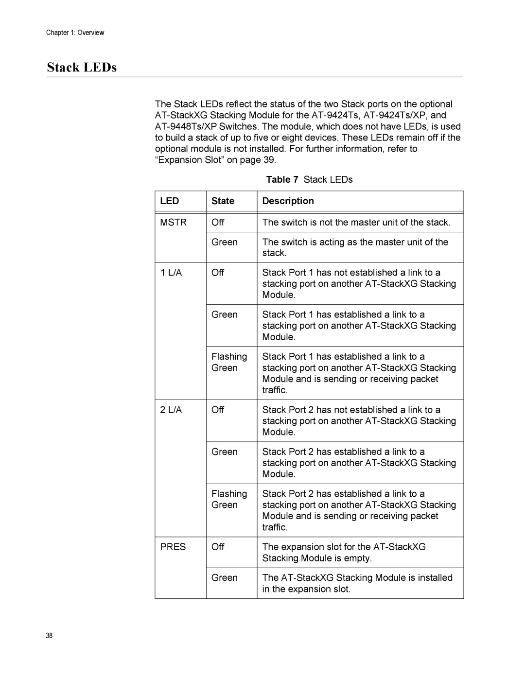
The Stack LEDs reflect the status of the two Stack ports on the optional
|
| Table 7 Stack LEDs |
|
|
|
LED | State | Description |
|
|
|
|
|
|
MSTR | Off | The switch is not the master unit of the stack. |
|
|
|
| Green | The switch is acting as the master unit of the |
|
| stack. |
|
|
|
1 L/A | Off | Stack Port 1 has not established a link to a |
|
| stacking port on another |
|
| Module. |
|
|
|
| Green | Stack Port 1 has established a link to a |
|
| stacking port on another |
|
| Module. |
|
|
|
| Flashing | Stack Port 1 has established a link to a |
| Green | stacking port on another |
|
| Module and is sending or receiving packet |
|
| traffic. |
|
|
|
2 L/A | Off | Stack Port 2 has not established a link to a |
|
| stacking port on another |
|
| Module. |
|
|
|
| Green | Stack Port 2 has established a link to a |
|
| stacking port on another |
|
| Module. |
|
|
|
| Flashing | Stack Port 2 has established a link to a |
| Green | stacking port on another |
|
| Module and is sending or receiving packet |
|
| traffic. |
|
|
|
PRES | Off | The expansion slot for the |
|
| Stacking Module is empty. |
|
|
|
| Green | The |
|
| in the expansion slot. |
|
|
|
38