Appendix A: Technical Specifications
RJ-45 Twisted Pair Port Pinouts
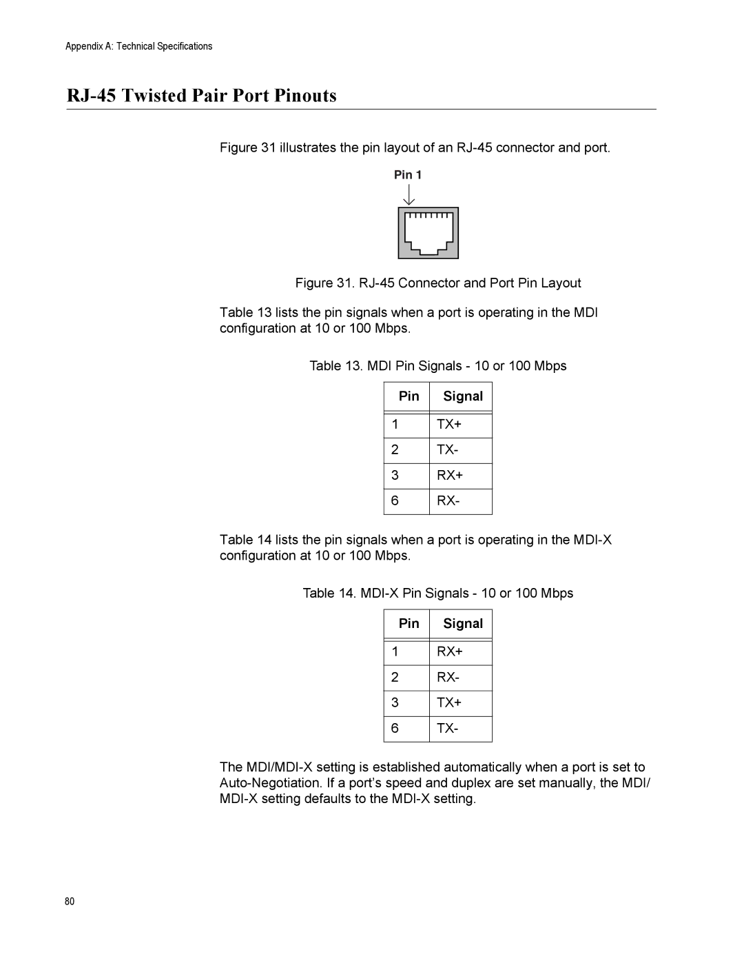
Figure 31 illustrates the pin layout of an RJ-45 connector and port.
Pin 1
Figure 31. RJ-45 Connector and Port Pin Layout
Table 13 lists the pin signals when a port is operating in the MDI configuration at 10 or 100 Mbps.
Table 13. MDI Pin Signals - 10 or 100 Mbps
Pin | Signal |
|
|
|
|
1 | TX+ |
|
|
2 | TX- |
|
|
3 | RX+ |
|
|
6 | RX- |
|
|
Table 14 lists the pin signals when a port is operating in the
Table 14.
Pin | Signal |
|
|
|
|
1 | RX+ |
|
|
2 | RX- |
|
|
3 | TX+ |
|
|
6 | TX- |
|
|
The
80