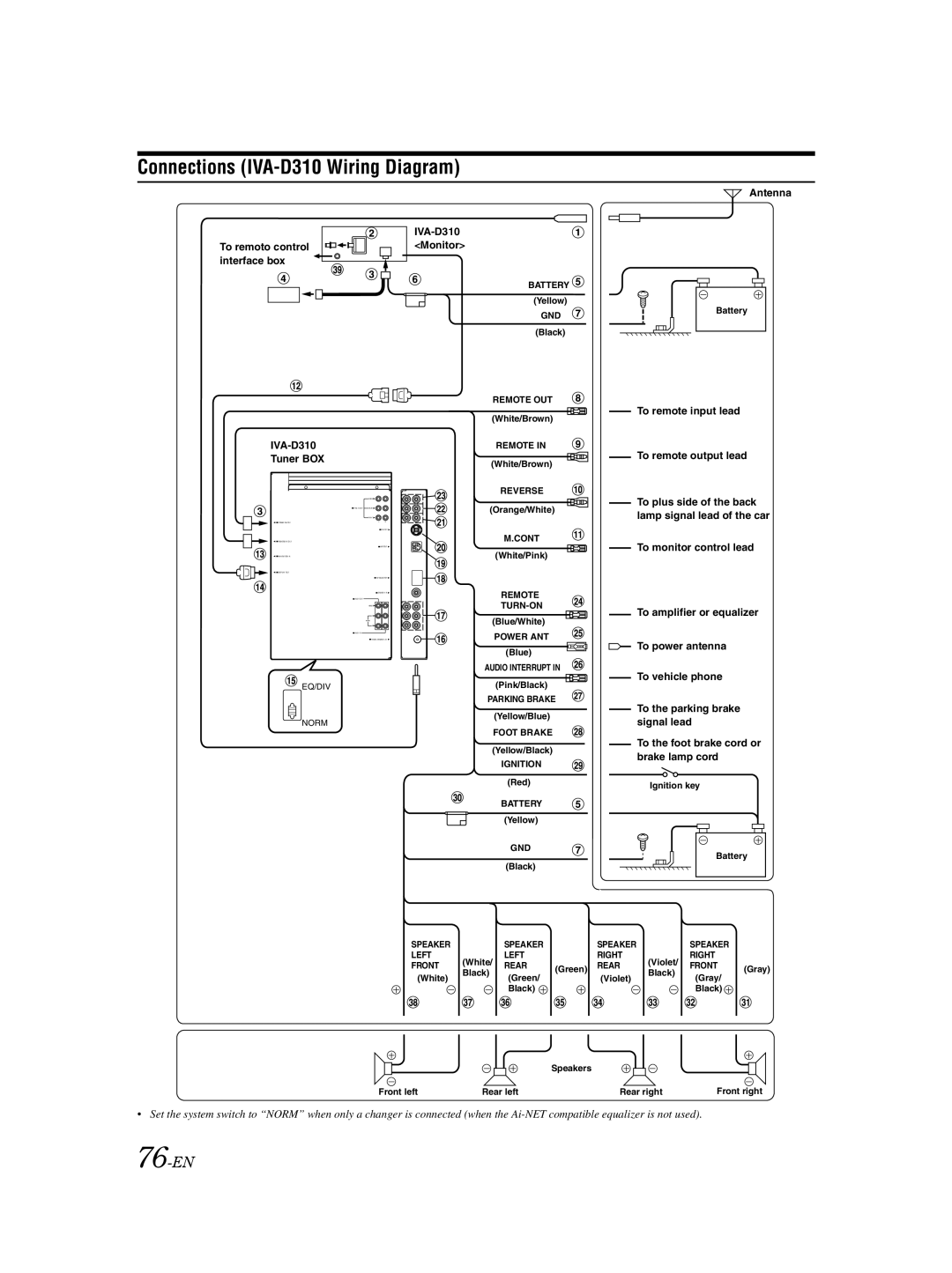
Connections (IVA-D310 Wiring Diagram)
To remoto control interface box
IVA-D310
Tuner BOX
SUBW.![]()
PRE IN/OUT | REAR |
FRONT ![]()
![]()
![]() POWER SUPPLY
POWER SUPPLY
![]()
![]()
![]()
![]() REMOTE IN/ OUT
REMOTE IN/ OUT
![]() EXT.OUT
EXT.OUT ![]()
![]()
![]() NAVIGATION IN
NAVIGATION IN
![]()
![]() DISPLAY OUT
DISPLAY OUT
![]() AV SELECTOR
AV SELECTOR ![]()
![]() CAMERA IN
CAMERA IN ![]()
![]() AUX OUT
AUX OUT
VIDEO ![]()
L![]()
AUDIO
R ![]()
![]() AUX IN
AUX IN
![]() RADIO ANTENNA IN
RADIO ANTENNA IN ![]()
![]() EQ/DIV
EQ/DIV
NORM
IVA-D310 <Monitor>
BATTERY ![]() (Yellow)
(Yellow)
GND (Black)
REMOTE OUT (White/Brown)
REMOTE IN (White/Brown)
REVERSE
(Orange/White)
M.CONT
(White/Pink)
REMOTE
POWER ANT (Blue)
AUDIO INTERRUPT IN (Pink/Black)
PARKING BRAKE (Yellow/Blue)
FOOT BRAKE
(Yellow/Black)
IGNITION (Red)
BATTERY (Yellow)
Antenna
Battery
To remote input lead
To remote output lead
To plus side of the back lamp signal lead of the car
To monitor control lead
To amplifier or equalizer
To power antenna
To vehicle phone
To the parking brake signal lead
To the foot brake cord or brake lamp cord
Ignition key
GND
(Black)
Battery
SPEAKER |
| SPEAKER | SPEAKER |
| SPEAKER |
| |
LEFT | (White/ | LEFT | RIGHT | (Violet/ | RIGHT |
| |
FRONT | REAR | (Green) REAR | FRONT | (Gray) | |||
Black) | Black) | ||||||
(White) | (Green/ | (Violet) | (Gray/ |
| |||
|
|
| |||||
|
| Black) |
|
| Black) |
|
Speakers
Front left | Rear left | Rear right | Front right |
•Set the system switch to “NORM” when only a changer is connected (when the
