As shipped, each ADC channel has a divide by 4 attenuator stage and a multiply by 2 amplifier stage. Thus for a signal applied to analog input pins on the backplane, a count of 4095 will correspond to a voltage of 8.192V.
For the DAC, analog output 0 has a multiply by 2 gain stage, so a count of 4095 corresponds to a voltage of 8.192V. Analog output 1 has a
Sample Programs
The sample program fir.c demonstrates the use of the ADC and DAC of the IOdimm. The digital I/O functions are demonstrated by the sample programs xor_iodimm.c and even_parity_iodimm.c.
fir.c will read analog input from a channel on the ADC. This input will be fed into a FIR filter, and then the output is written to the DAC. The source code for fir.c is available in /opt/samples/card_specific/
iodimm/fir.
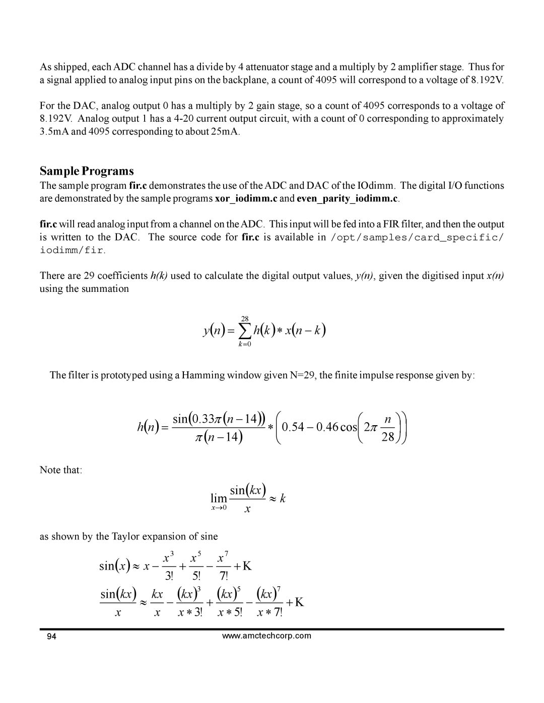
There are 29 coefficients h(k) used to calculate the digital output values, y(n), given the digitised input x(n) using the summation
28
y(n) = ∑h(k )∗ x(n − k )
k=0
The filter is prototyped using a Hamming window given N=29, the finite impulse response given by:
h(n) = | sin(0.33π (n −14)) | | | n | ||||
|
|
| ∗ 0.54 | − 0.46 cos 2π |
| | ||
π (n | −14) | 28 | ||||||
| | | | |||||
Note that:
lim sin(kx) ≈ k
x→0 x
as shown by the Taylor expansion of sine
sin(x) ≈ x − | x3 | + | x5 |
| − | x7 | + Κ |
|
|
| |||||||
|
| 7! |
|
|
| ||||||||||||
|
|
|
|
| 3! | 5! |
|
|
|
|
|
|
|
| |||
sin(kx) | ≈ | kx | − | (kx)3 | + | (kx)5 | − | (kx)7 | + Κ | ||||||||
|
|
|
|
|
|
|
|
|
|
| |||||||
x |
| x | x ∗ 3! | x ∗ 5! | x ∗ 7! | ||||||||||||
|
|
|
|
| |||||||||||||
94 | www.amctechcorp.com |