9

Front Panel

MasterSwitch 100V – User Guide

9


The primary feature of the MasterSwitch is the programmable control of eight power outlets using embedded Web-based control, SNMP control, or the console program via telnet or the onboard serial port. Two connectors provide for the physical link for programming:

nA built-in serial port, which connects a terminal (or terminal emulator) to access the console program.

nA built-in 10Base-T network connector, which connects the MasterSwitch to an Ethernet LAN to allow using the embedded Web control, telnet, or SNMP to configure the MasterSwitch. The MasterSwitch must connect to an Ethernet LAN to use telnet, SNMP or embedded Web control.

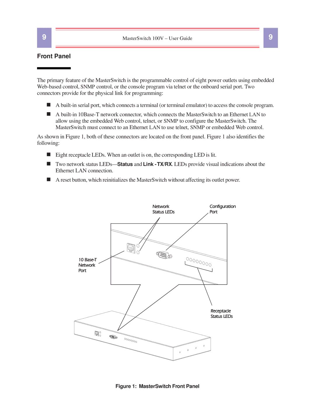
As shown in Figure 1, both of these connectors are located on the front panel. Figure 1 also identifies the following:

nEight receptacle LEDs. When an outlet is on, the corresponding LED is lit.

nTwo network status LEDs— Status and Link - TX/RX. LEDs provide visual indications about the Ethernet LAN connection.

nA reset button, which reinitializes the MasterSwitch without affecting its outlet power.

Figure 1: MasterSwitch Front Panel

Page 9
Image 9
American Power Conversion AP9210 manual MasterSwitch Front Panel