MVP-7500/8400
AMX Limited Warranty and Disclaimer
FCC Information
Page
Table of Contents
Upgrading MVP Firmware
Panel Calibration 141
Appendix B Wireless Technology 151
FG5965-01
MVP Modero Viewpoint Wireless Touch Panels
Overview
MVP Specifications
MVP Specifications
Weight
Memory factory default
Specifications
MVP-7500 LCD
Certifications
Included Accessories
Other AMX Equipment
FG2255-07
Installing MVP-BP Batteries
MVP-BP Power Pack
MVP-BP Specifications
MVP-BP Specifications
If you are only using one battery, use Battery Slot #1
Accessing the MVP’s Internal Components
Installing the NXA-CFSP Compact Flash Card
NXA-CFSP Compact Flash
Compact Flash Card Security
Installing the Compact Flash Upgrade Card
Removing the Installed Card
Care When Handling the Card
Page
802.11b Wireless Interface Card
Wireless Interface Cards
Specifications
802.11b Wireless Interface Card Specifications
NXA-WC80211GCF 802.11g Wireless Interface Card
NXA-WC80211GCF Specifications
Radio Technology
Wireless LAN Security
Receiver Sensitivity
RF Frequency Ranges
Access the MVP’s Internal Components
Installing the 802.11g Card and Antenna
Preparing the MVP’s Rear Housing
Firmware Requirements
Installing the Mounting Template
Installing the NXA-WC80211GCF
Closing and Securing the MVP Enclosure
Outer housing latch attachment locations
Wireless Interface Cards
Accessing the Setup and Protected Setup Pages
Configuring Communications
Modero Setup and System Settings
Hot Swapping
Wireless Settings Page Wireless Access Overview
Setting the Panel’s Device Number
Wireless communication using a Dhcp Address
Configuring a Wireless Network Access
Configure the Panel’s Wireless IP Settings
Using the Site Survey tool
Wireless communication using a Static IP Address
Site Survey
Configure the Card’s Wireless Security Settings
MVP connection IP info Wireless Card security settings
Required Information
By default, this field displays
Automatically set Ssid
Select Wireless Settings
Manually set Ssid
Locate the Wireless Security section FIG
These WEP Key identifier values must match for both devices
WEP Key # Keyboard
Select System Settings
Choose a Master Connection Mode
System Settings page USB Connection
USB driver installation popup window
Configure a Virtual NetLinx Master using NetLinx Studio
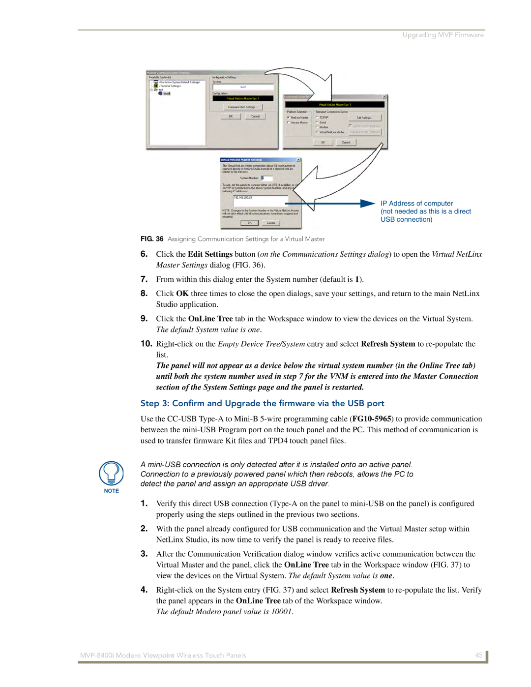
Assigning Communication Settings for a Virtual Master
Ethernet
Mode Description Procedures
Master Connection to a Virtual Master via Ethernet
Connection Modes
Configuring Communications
Ethernet
G4 Web Control
Using G4 Web Control to Interact with a G4 Panel
Configuring Communications
Using your NetLinx Master to control the G4 panel
Web Control VNC installation and Password entry screens
Configuring Communications
Upgrading MVP Firmware
Prepare Studio for communication via the USB port
Configure the panel for a USB Connection Type
Upgrading the Modero Firmware via the USB port
Default Modero panel value is
Confirm and Upgrade the firmware via the USB port
Using USB for a Virtual Master transfer
Prepare the Docking Station for firmware transfer via USB
Upgrading the Docking Station Firmware via USB
Batteries
Upgrade the Docking Station firmware via USB
Device and System values
Upgrading MVP Firmware
Setup Pages
Setup Pages
Features on this page include
Setup
Timeout
Display Timeout
Connection Status
Inactivity Page Flip
Project Information
Navigation Buttons
Project Information
Panel Information
Panel Information
RAM
Time & Date Setup
Time & Date Setup
Volume
Audio Adjustments/Volume
Features on these pages include
Supported WAV Sample Rates
WAV files Supported sample rates
Batteries
Low Battery Warning
Batteries
Limit
Charge Status fields are left blank
Battery Status
Protected Setup
Protected Setup Pages
Features on the Protected Setup page include
Docking Station
Protected Setup Navigation Buttons
Reboot Panel
G4 Web Control
G4 Web Control Settings
G4 Web Control
Password Setup
Password Setup
G4 Web Control Timeout
Panel Password
Calibration
User Access
IP Settings
Wireless Settings
Wireless Settings
Wireless Security
Access Point MAC
Address
Network Name Ssid WAP names
RF Link Info
Site Survey
Wireless Security Support
Wireless Security
802.11b Wi-Fi CF card Open Clear Text
802.11g Wi-Fi CF card Open Clear Text
Save/Cancel
Open Clear Text Settings
Open Clear Text Settings
WEP 64 / WEP
Static WEP Settings
Static WEP Settings
Authentication
Default Key
Generate Passphrase
WEP Keys
Wireless Settings page WPA-PSK Settings
WPA-PSK Settings
Password/Pass Phrase
EAP-LEAP Settings
WPA-PSK Settings
Identity
EAP-LEAP Settings
Password
EAP-LEAP sample Cisco System Security
EAP-FAST Settings
Anonymous Identity
EAP-FAST Settings
Automatic PAC
Provisioning
PAC File Location
EAP-PEAP Settings
Been Disabled
Inner Authentication Type
EAP-PEAP Settings
Certificate Authority
Peap Version
Ssid Service Set Identifier
EAP-TTLS Settings
EAP-TTLS Settings
MSCHAPv2 default because its the most common
EAP-TLS Settings
EAP-TLS Settings
Client Certificate Configuration
Client certificate configuration
Private Key password
Client Certificate
Certificates and their Extensions
Configuration Field Name Certificate File Type Supported
Certificate Types Supported by the Modero Firmware
Certificate Type Possible File Extensions
System Settings Page Elements
System Settings
Elements of this page include
Master Connection
Ethernet Only disabled when USB is selected
Following EAP types all support a server certificate
EAP Security & Server Certificates Overview
Setup Pages MVP Modero ViewPoint Touch Panels
Commands
Commands
Programming
Button Assignments
@DPG
@CPG
@PDR
@PHE
@PPA
@PHT
@PPF
@PPG
@PPM
@PPK
@PPN
@PPT
@PSE
@PPX
@PSP
@PST
Ppon
Ppof
Ppog
RGB triplets and names for basic 88 colors
Programming Numbers
RGB Values for all 88 Basic Colors
Index No Name Red Green Blue
RGB Values for all 88 Basic Colors
Font ID Font type Size
Default Font Styles and ID Numbers
Font styles and ID numbers
Border Styles and Programming Numbers
Border styles and Programming numbers
TPD4 Border Styles by Name
Border styles
TPD4 Border Styles by Name
Button Commands
Button Commands
Sendcommand Panel,ANI-500,1,25,100
ANI
BAU
APF
BAT
BCT
BCB
BCF
BFB
BDO
BIM
Entry is required
BMC
BLN
BMF-vt addr range,button states range,data
BMC
BMF
Cont
BML
BMI
BMP
BNC
BOP
BNN
BNT
BPP
BOR
BOS
BSF
BRD
BSM
BSO
BVN
BVL
BVP
BVT
DLD
CPF
DPF
ENA
GIV
FON
GDI
GLL
GLH
GRD
GRU
IRM
GSN
ICO
JSI
JSB
MBT
JST
Pass data
MDC
TEF
TEC
Effect names
TXT
MVP Panel Lock Passcode Commands
MVP Panel Lock Passcode commands
Miscellaneous MVP Strings back to the Master
MVP Strings to Master
Text Effects
Text Effects Names
LPR
LPS
Defineevent
Button Query Commands
All custom events have the following 6 fields
Button Query Commands
Custom Event Fields
?BCB
?BCT
?BCF
?BOP
?BMP
?BWW
?BRD
?ICO
?FON
?JSI
?JSB
?TEC
?JST
Send Command Panel,?TXT-529,1
Send Command Panel,?TEF-529,1
?TEF
?TEF-vt addr range,button states range
Panel Runtime Operations
Panel Runtime Operation Commands
@AKR
@AKP
Beep
Brit
@EKP
Setup
Pkeyp
@PKP
@TKP
@SOU
Tpageon
Tpageoff
Input Commands
Input Commands
These Send Commands are case insensitive
Following is a list of G4 compatible embedded codes
Embedded codes
Embedded Codes
Decimal numbers Hexidecimal values Virtual keystroke
Panel Setup Commands
Panel Setup Commands
These commands are case insensitive
Dynamic Image Commands
Dynamic Image Commands
RAF-resource name,data
Intercom Commands
Intercom Commands
Following is a list of Intercom Commands
ICM-LISTEN
ICM-TALK
Calibrating the MVP Panels
Panel Calibration
Touch Panel Calibration Screens
Testing your Calibration
If Calibration Is Not Working
Page
Text Formatting Codes for Bargraphs/Joysticks
Appendix a Text Formatting
Bargraph Text Code Inputs
Formatting Code Operations
Text Area Input Masking
With this feature, it is not necessary to
Input mask character types
Character Types
Input mask next field characters
Input mask ranges
Input mask operations
Input mask literals
Following are some common input masking examples
Input mask output examples
Output Examples
Common Name Input Mask
Special escape sequences
URL Resources
Escape Sequences
Sequence Panel Information
Page
Overview of Wireless Technology
Appendix B Wireless Technology
802.1x
Terminology
Tkip
WPA2
EAP characteristics
EAP Authentication
EAP Method Characteristics
Method Credential Type Authentication Pros Cons
EAP security method in process
EAP communication overview
AMX Certificate Upload Utility
Configuring your G4 Touch Panel for USB Communication
Setup the Panel and PC for USB Communication
Confirm the Installation of the USB Driver on the PC
How to Upload a Certificate File
160 MVP-7500/8400 Modero Viewpoint Wireless Touch Panels
Page
Page
Batteries Will Not Hold Or Take a Charge
Appendix C Troubleshooting
Panel Doesn’t Respond To Touches
MVP Can’t Obtain a Dhcp Address
Modero Panel Isn’t Appearing In The Online Tree Tab
My WEP Doesn’t Seem To Be Working
NetLinx Studio Only Detects One Of My Connected Masters
Only One Modero Panel In My System Shows Up
Page
Page
It’s Your World Take Control