Installation
Installation
Wiring and Connections
To avoid any damage to the electronic component, installation must be performed in an ESD safe environment.
Do not connect power to the
The
|
|
|
NetLinx Master |
| |
|
|
|
PoE injector ![]()
![]()
KNX
Control
Bus
Ethernet 10/100 |
FIG. 1 NXB-KNX installation
After you have completed the installation, consult the Configuration section on page 5.
Ethernet 10/100 Base-T RJ-45 Wiring Configuration
The table below describes the pinouts, signals, and pairing for the Ethernet 10/100
Ethernet Pinouts and Signals
Pin | Signals | Connections | Pairing | Color | ||
1 | TX + | 1 | 1 | 1 | 2 | |
2 | TX - | 2 | 2 |
|
| Orange |
3 | RX + | 3 | 3 | 3 | 6 | |
4 | no connection | 4 | 4 |
|
| Blue |
5 | no connection | 5 | 5 |
|
| |
6 | RX - | 6 | 6 |
|
| Green |
7 | no connection | 7 | 7 |
|
| |
8 | no connection | 8 | 8 |
|
| Brown |
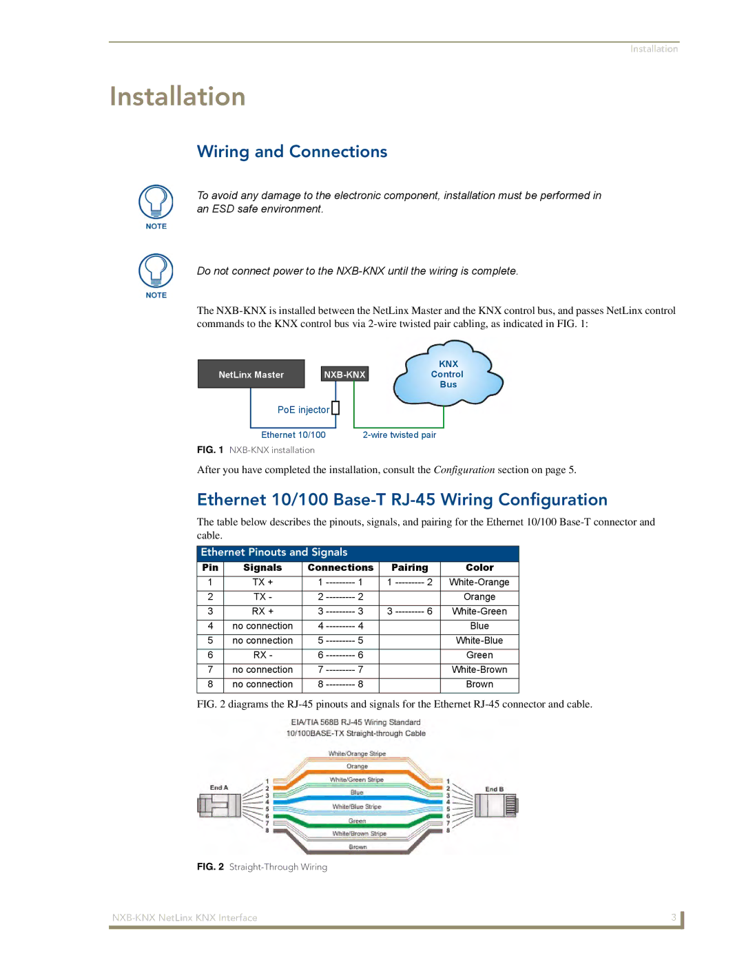
FIG. 2 diagrams the RJ-45 pinouts and signals for the Ethernet RJ-45 connector and cable.
FIG. 2 |
|
3 |