EZ-KIT Lite Hardware Reference
To use the DAI for a different purpose, disable any signal driving the DAI pins with a switch (see “Codec Setup Switch (SW3)” on page
All of the DAI signals are available externally via the expansion interface connectors
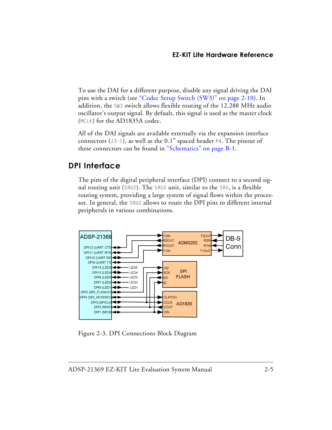
DPI Interface
The pins of the digital peripheral interface (DPI) connect to a second sig- nal routing unit (SRU2). The SRU2 unit, similar to the SRU, is a flexible routing system, providing a large system of signal flows within the proces- sor. In general, the SRU2 allows to route the DPI pins to different internal peripherals in various combinations.
|
|
|
|
|
|
|
|
|
|
|
|
|
|
|
|
|
|
|
|
|
|
|
|
|
|
|
|
|
|
|
|
|
|
|
|
|
|
|
|
|
| T2IN |
|
| T2OUT |
| |
|
|
|
|
|
|
|
|
|
|
|
|
|
|
|
|
|
|
|
|
|
| ||
|
|
|
|
|
|
|
|
|
|
|
|
|
|
|
|
|
|
| R2OUT | ADM3202 | R2IN |
| |
|
|
|
|
|
|
|
|
|
|
|
|
|
|
|
|
|
|
|
| ||||
DPI12 (UART CTS) |
|
|
|
|
|
|
|
|
|
|
|
|
|
|
|
|
|
| R1OUT |
|
| R1IN |
|
|
|
|
|
|
|
|
|
|
|
|
|
|
|
|
|
|
| T1IN |
|
| T1OUT |
| |
DPI11 (UART RTS) |
|
|
|
|
|
|
|
|
|
|
|
|
|
|
|
|
|
|
|
|
| ||
|
|
|
|
|
|
|
|
|
|
|
|
|
|
|
|
|
|
|
|
|
|
| |
DPI10 (UART RX) |
|
|
|
|
|
|
|
|
|
|
|
|
|
|
|
|
|
|
|
|
|
|
|
|
|
|
|
|
|
|
|
|
|
|
|
|
|
|
|
|
|
|
|
|
|
| |
DPI9 (UART TX) |
|
|
|
|
|
|
|
|
|
|
|
|
|
|
|
|
|
|
|
|
|
|
|
|
|
|
|
|
|
|
|
|
|
|
|
|
|
|
|
|
|
|
|
|
|
| |
DPI14 (LED5) |
|
|
|
|
|
| LED5 |
|
|
|
|
|
|
|
|
| CS/ | SPI |
|
|
| ||
|
|
|
|
|
|
|
|
|
|
|
|
| |||||||||||
DPI13 (LED4) |
|
|
|
|
|
| LED4 |
|
|
|
|
|
|
|
|
| SCK |
|
|
| |||
DPI8 (LED3) |
|
|
|
|
|
| LED3 |
|
|
|
|
|
|
|
|
| SO | FLASH |
|
|
| ||
|
|
|
|
|
|
|
|
|
|
|
|
|
|
|
|
|
| ||||||
DPI7 (LED2) |
|
|
|
|
|
| LED2 |
|
|
|
|
|
|
|
|
| SI |
|
|
|
| ||
|
|
|
|
|
|
|
|
|
|
|
| ||||||||||||
DPI6 (LED1) |
|
|
|
|
|
| LED1 |
|
|
|
|
|
|
|
|
|
|
|
|
|
| ||
|
|
|
|
|
|
|
|
|
|
| |||||||||||||
DPI5 (SPI_FLASHCS) |
|
|
|
|
|
|
|
|
|
|
|
|
|
|
|
|
|
|
|
|
|
|
|
|
|
|
|
|
|
|
|
|
|
|
|
|
|
|
|
|
|
|
|
|
|
| |
DPI4 (SPI_AD1835CS) |
|
|
|
|
|
|
|
|
|
|
|
|
|
|
|
|
|
| CLATCH |
|
| ||
|
|
|
|
|
|
|
|
|
|
|
|
|
|
|
|
|
|
|
| ||||
DPI3 (SPICLK) |
|
|
|
|
|
|
|
|
|
|
|
|
|
|
|
|
|
| CCLK | AD1835 |
|
| |
|
|
|
|
|
|
|
|
|
|
|
|
|
|
|
|
|
|
|
| ||||
DPI2 (MISO) |
|
|
|
|
|
|
|
|
|
|
|
|
|
|
|
|
|
| COUT |
|
|
|
|
|
|
|
|
|
|
|
|
|
|
|
|
|
|
|
|
|
|
|
|
|
| ||
DPI1 (MOSI) |
|
|
|
|
|
|
|
|
|
|
|
|
|
|
|
|
|
| CIN |
|
|
|
|
|
|
|
|
|
|
|
|
|
|
|
|
|
|
|
|
|
|
|
|
|
| ||
|
|
|
|
|
|
|
|
|
|
|
|
|
|
|
|
|
|
|
|
|
|
|
|
Figure 2-3. DPI Connections Block Diagram
|