Switch Settings
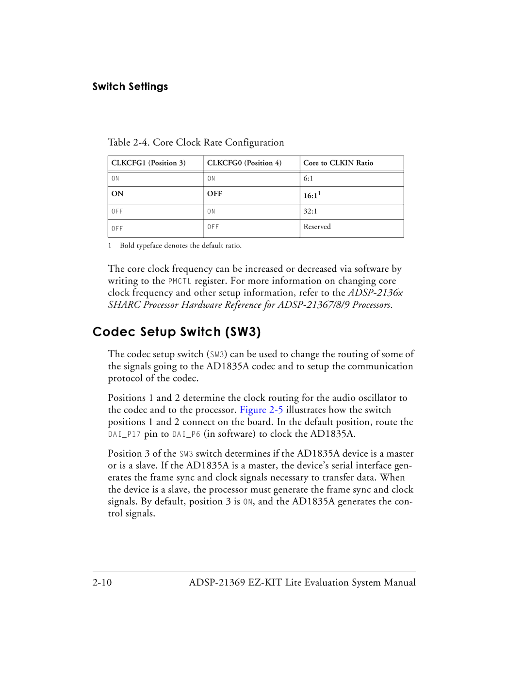
Table 2-4. Core Clock Rate Configuration
CLKCFG1 (Position 3) | CLKCFG0 (Position 4) | Core to CLKIN Ratio |
|
|
|
|
|
|
ON | ON | 6:1 |
|
|
|
ON | OFF | 16:11 |
OFF | ON | 32:1 |
|
|
|
OFF | OFF | Reserved |
|
|
|
1 Bold typeface denotes the default ratio.
The core clock frequency can be increased or decreased via software by writing to the PMCTL register. For more information on changing core clock frequency and other setup information, refer to the
Codec Setup Switch (SW3)
The codec setup switch (SW3) can be used to change the routing of some of the signals going to the AD1835A codec and to setup the communication protocol of the codec.
Positions 1 and 2 determine the clock routing for the audio oscillator to the codec and to the processor. Figure
Position 3 of the SW3 switch determines if the AD1835A device is a master or is a slave. If the AD1835A is a master, the device’s serial interface gen- erates the frame sync and clock signals necessary to transfer data. When the device is a slave, the processor must generate the frame sync and clock signals. By default, position 3 is ON, and the AD1835A generates the con- trol signals.