EZ-KIT Lite Hardware Reference
AD1835A Codec |
DAI_P6
DAI_P17
MCLK
12.288MHz
OSC
SW3.1
SW3.2
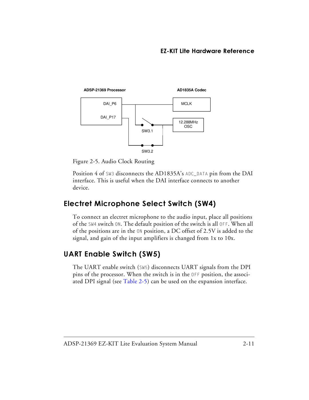
Figure 2-5. Audio Clock Routing
Position 4 of SW3 disconnects the AD1835A’s ADC_DATA pin from the DAI interface. This is useful when the DAI interface connects to another device.
Electret Microphone Select Switch (SW4)
To connect an electret microphone to the audio input, place all positions of the SW4 switch ON. The default position of the switch is all OFF. When all of the positions are in the ON position, a DC offset of 2.5V is added to the signal, and gain of the input amplifiers is changed from 1x to 10x.
UART Enable Switch (SW5)
The UART enable switch (SW5) disconnects UART signals from the DPI pins of the processor. When the switch is in the OFF position, the associ- ated DPI signal (see Table