EZ-KIT Lite Hardware Reference
ELVIS Oscilloscope Configuration Switch (SW1)
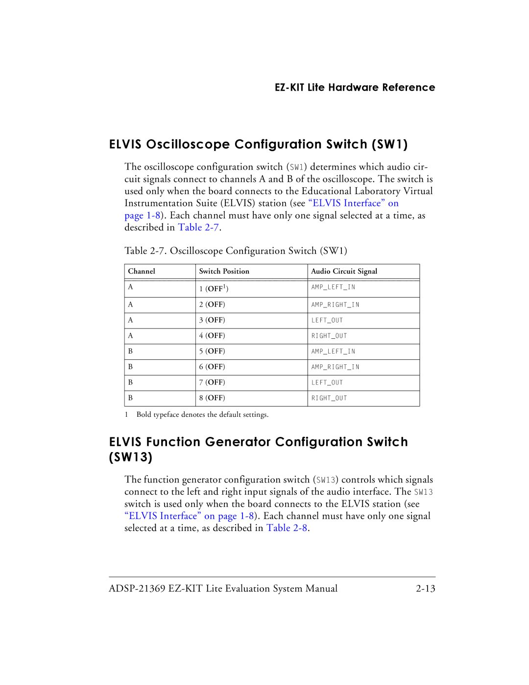
The oscilloscope configuration switch (SW1) determines which audio cir- cuit signals connect to channels A and B of the oscilloscope. The switch is used only when the board connects to the Educational Laboratory Virtual Instrumentation Suite (ELVIS) station (see “ELVIS Interface” on
page
Table
Channel | Switch Position | Audio Circuit Signal | |
|
|
|
|
|
|
|
|
A | 1 | (OFF1) | AMP_LEFT_IN |
A | 2 | (OFF) | AMP_RIGHT_IN |
|
|
|
|
A | 3 | (OFF) | LEFT_OUT |
|
|
|
|
A | 4 | (OFF) | RIGHT_OUT |
|
|
|
|
B | 5 | (OFF) | AMP_LEFT_IN |
|
|
|
|
B | 6 | (OFF) | AMP_RIGHT_IN |
|
|
|
|
B | 7 | (OFF) | LEFT_OUT |
|
|
|
|
B | 8 | (OFF) | RIGHT_OUT |
|
|
|
|
1 Bold typeface denotes the default settings.
ELVIS Function Generator Configuration Switch (SW13)
The function generator configuration switch (SW13) controls which signals connect to the left and right input signals of the audio interface. The SW13 switch is used only when the board connects to the ELVIS station (see “ELVIS Interface” on page