Switch Settings
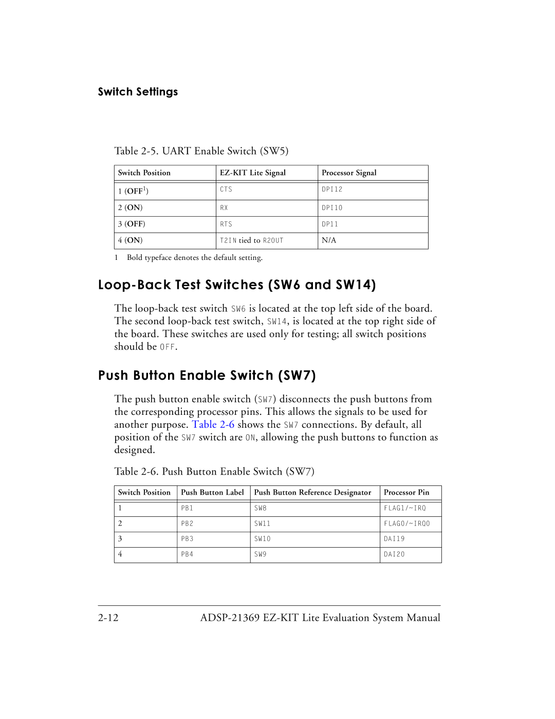
Table 2-5. UART Enable Switch (SW5)
Switch Position | Processor Signal | ||
|
|
|
|
|
|
|
|
1 | (OFF1) | CTS | DPI12 |
2 | (ON) | RX | DPI10 |
|
|
|
|
3 | (OFF) | RTS | DP11 |
|
|
|
|
4 | (ON) | T2IN tied to R2OUT | N/A |
|
|
|
|
1 Bold typeface denotes the default setting.
Loop-Back Test Switches (SW6 and SW14)
The
Push Button Enable Switch (SW7)
The push button enable switch (SW7) disconnects the push buttons from the corresponding processor pins. This allows the signals to be used for another purpose. Table
Table
Switch Position | Push Button Label | Push Button Reference Designator | Processor Pin |
|
|
|
|
|
|
|
|
1 | PB1 | SW8 | FLAG1/~IRQ |
|
|
|
|
2 | PB2 | SW11 | FLAG0/~IRQ0 |
|
|
|
|
3 | PB3 | SW10 | DAI19 |
|
|
|
|
4 | PB4 | SW9 | DAI20 |
|
|
|
|