LEDs and Push Buttons
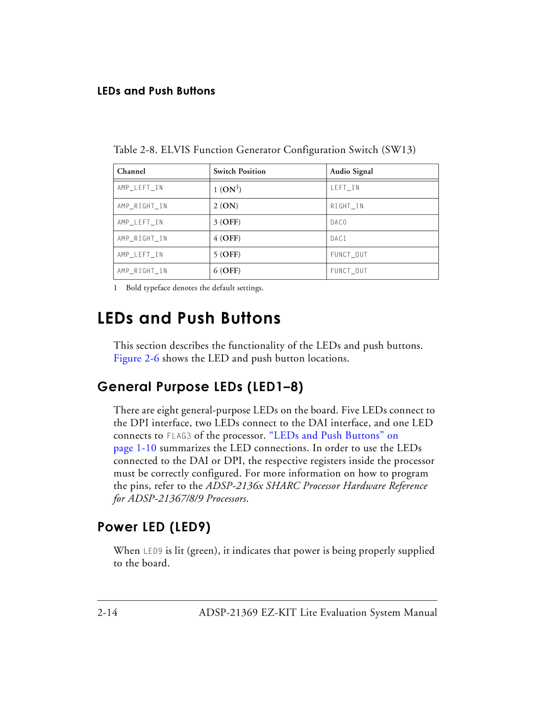
Table 2-8. ELVIS Function Generator Configuration Switch (SW13)
Channel | Switch Position | Audio Signal | |
|
|
|
|
|
|
|
|
AMP_LEFT_IN | 1 | (ON1) | LEFT_IN |
AMP_RIGHT_IN | 2 | (ON) | RIGHT_IN |
|
|
|
|
AMP_LEFT_IN | 3 | (OFF) | DAC0 |
|
|
|
|
AMP_RIGHT_IN | 4 | (OFF) | DAC1 |
|
|
|
|
AMP_LEFT_IN | 5 | (OFF) | FUNCT_OUT |
|
|
|
|
AMP_RIGHT_IN | 6 | (OFF) | FUNCT_OUT |
|
|
|
|
1 Bold typeface denotes the default settings.
LEDs and Push Buttons
This section describes the functionality of the LEDs and push buttons. Figure
General Purpose LEDs (LED1–8)
There are eight
page
Power LED (LED9)
When LED9 is lit (green), it indicates that power is being properly supplied to the board.
