Introduction (cont.)
Installation with an engine generator set
(figure 15)
If a
It is disconnected when Mains power is restored.
With such a system, the required battery time may be reduced to the time necessary for starting and bringing on line the
The battery supplies power to the inverter during the transfers: Mains ➔ generator and generator ➔ Mains.
The transfer sequences described: Mains ➔ battery ➔ generator and generator ➔ battery ➔ Mains are fully automatic. They in no way affect the load and require no manual operation by the user.
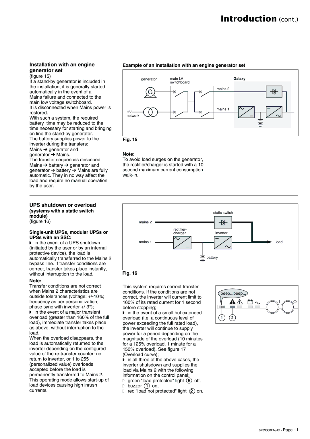
Example of an installation with an engine generator set
generator | main LV | Galaxy |
| switchboard |
|
G |
| mains 2 |
|
| |
HV |
| mains 1 |
|
| |
network |
|
|
Fig. 15
Note:
To avoid load surges on the generator, the rectifier/charger is started with a 10 second maximum current consumption
UPS shutdown or overload
(systems with a static switch module)
(figure 16)
◗ in the event of a UPS shutdown |
(initiated by the user or by an internal |
protective device), the load is |
automatically transferred to the Mains 2 |
bypass line. If transfer conditions are |
correct, transfer takes place instantly, |
static switch
mains 2
rectifier-
chargerinverter
mains 1
![]() battery
battery
load
without interruption to the load. |
Note:
Transfer conditions are not correct when Mains 2 characteristics are outside tolerances (voltage:
◗in the event of a major transient overload (greater than 160% of the full load), immediate transfer takes place as above, without interruption to the load.
When the overload disappears, the load is automatically returned to the inverter depending on the configured value of the
Fig. 16
This system requires correct transfer conditions. If the conditions are not correct, the inverter will current limit to 160% of its rated current for 1 second before stopping;
◗in the event of a small but extended overload (i.e. a continuous level of power exceeding the full rated load), the inverter will continue to supply power for a period depending on the magnitude of the overload (10 minutes for a 125% overload, 1 minute for a 150% overload). See figure 17 (Overload curve);
◗in all three of the above cases, the inverter shutsdown and supplies the load via Mains 2 with the following information on the control panel:
◗ green "load protected" light 5 off,
◗buzzer 1 on,
◗red "load not protected" light 2 on.
beep...beep...
! | ! | + – |
|
|
1 2
IO
6739380EN/JC - Page 11