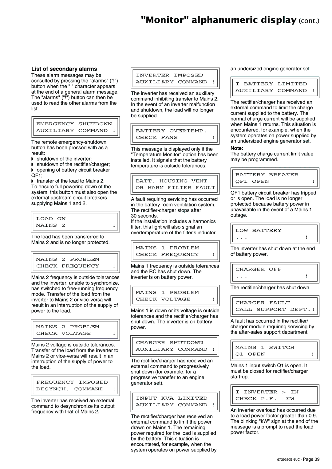
"Monitor" alphanumeric display (cont.)
List of secondary alarms
These alarm messages may be consulted by pressing the "alarms" ("!") button when the "!" character appears at the end of a general alarm message. The "alarms" ("!") button can then be used to read the other alarms from the list.
EMERGENCY SHUTDOWN
AUXILIARY COMMAND !
The remote
◗shutdown of the inverter;
◗shutdown of the rectifier/charger;
◗opening of battery circuit breaker QF1;
◗transfer of the load to Mains 2. To ensure full powering down of the system, this button must also open the external upstream circuit breakers supplying Mains 1 and 2.
LOAD ON
MAINS 2 | ! |
The load has been transferred to Mains 2 and is no longer protected.
MAINS 2 PROBLEM
CHECK FREQUENCY !
Mains 2 frequency is outside tolerances and the inverter, unable to synchronize, has switched to
MAINS 2 PROBLEM
CHECK VOLTAGE | ! |
Mains 2 voltage is outside tolerances. Transfer of the load from the inverter to Mains 2 or
FREQUENCY IMPOSED
DESYNCH. COMMAND !
The inverter has received an external command to desynchronize its output frequency with that of Mains 2.
INVERTER IMPOSED
AUXILIARY COMMAND !
The inverter has received an auxiliary command inhibiting transfer to Mains 2. In the event of an inverter malfunction and shutdown, the load will no longer be supplied.
BATTERY OVERTEMP.
CHECK FANS | ! |
This message is displayed only if the "Temperature Monitor" option has been installed. It signals that the battery temperature is outside tolerances.
BATT. HOUSING VENT
OR HARM FILTER FAULT!
A fault requiring servicing has occurred in the battery room ventilation system. The
30 seconds.
If the installation includes a harmonics filter, this light will also signal an overtemperature of the filter’s inductor.
MAINS 1 PROBLEM
CHECK FREQUENCY !
Mains 1 frequency is outside tolerances and the RC has shut down. The inverter is on battery power.
MAINS 1 PROBLEM
CHECK VOLTAGE | ! |
Mains 1 is down or its voltage is outside tolerances and the rectifier/charger has shut down. The inverter is on battery power.
CHARGER SHUTDOWN
AUXILIARY COMMAND !
The rectifier/charger has received an external command to progressively shut down (for example, for a progressive transfer to an engine generator set).
INPUT KVA LIMITED
AUXILIARY COMMAND !
The rectifier/charger has received an external command to limit the power drawn on Mains 1. The remaining power required for the load is supplied by the battery. This situation is encountered, for example, when the system operates on power supplied by
an undersized engine generator set.
I BATTERY LIMITED
AUXILIARY COMMAND !
The rectifier/charger has received an external command to limit the charge current supplied to the battery. The normal charge current will be supplied when Mains 1 returns. This situation is encountered, for example, when the system operates on power supplied by an undersized engine generator set.
Note:
The battery charge current limit value may be programmed.
BATTERY BREAKER
QF1 OPEN | ! |
QF1 battery circuit breaker has tripped or is open. The load is no longer protected because battery power in unavailable in the event of a Mains 1 outage.
LOW BATTERY
...!
The inverter has shut down at the end of battery power.
CHARGER OFF
...!
The rectifier/charger has shut down.
CHARGER FAULT
CALL SUPPORT DEPT.!
A fault has occurred in the rectifier/ charger module requiring servicing by the
MAINS 1 SWITCH
Q1 OPEN | ! |
Mains 1 input switch Q1 is open. It must be closed for rectifier/charger
I INVERTER > IN
CHECK P.F. KW
An inverter overload has occurred due to a load power factor greater than 0.9. The blinking "kW" sign at the end of the message is a prompt to read the load power factor.
6739380EN/JC - Page 39
