Maintenance
Maintenance configuration
Single-unit or single modular UPS (figure 29)
During maintenance, the UPS must be isolated from Mains 1 and 2, the battery and the load.
◗inverter isolation
Proceed in the following order:
◗shut down the inverter (press the "inverter off" button 7 for 3 seconds),
◗close bypass switch Q3BP,
◗open isolating switches Q5N, Q4S, QF1 and Q1.
The UPS is powered down once the capacitors have discharged (a few minutes);
◗start-up
mains 2
Q1
mains 1
Q3BP
static switch
Q4S
rectifier-
chargerinverter
Q5N
load
QF1
battery
Following servicing, proceed in the following order:
◗close switch Q1, then after approximately ten seconds, switches QF1, Q5N and Q4S,
◗open bypass switch Q3BP,
◗start the inverter (press the "inverter on" button 6 ).
Fig. 29 |
|
Caution: | ◗ to avoid interrupting the load, the |
◗ work should be carried out in | various switching operations must |
accordance with applicable safety | be carried out in the correct order. |
regulations; | Operations are explained in |
| diagrams placed next to the |
| switches. |
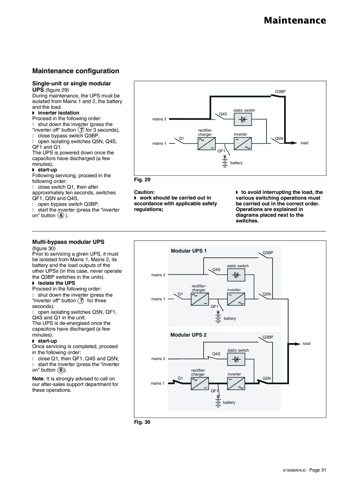
Multi-bypass modular UPS
(figure 30)
Prior to servicing a given UPS, it must be isolated from Mains 1, Mains 2, its
Modular UPS 1 | Q3BP |
|
battery and the load outputs of the other UPSs (in this case, never operate the Q3BP switches in the units).
◗isolate the UPS
Proceed in the following order:
◗ shut down the inverter (press the |
"inverter off" button 7 for three |
seconds); |
◗ open isolating switches Q5N, QF1, |
Q4S and Q1 in the unit. |
The UPS is |
capacitors have discharged (a few |
mains 2
Q1
mains 1
static switch
Q4S
rectifier-
chargerinverter
Q5N
QF1
battery
minutes). |
◗ |
Once servicing is completed, proceed in the following order:
◗close Q1, then QF1, Q4S and Q5N;
◗start the inverter (press the “inverter on” button 6 ).
Note. It is strongly advised to call on our
Modular UPS 2
mains 2
rectifier- charger
Q1
mains 1
Q4S
QF1
Q3BP
load
static switch
inverter
Q5N
battery
Fig. 30
6739380EN/JC - Page 31