"Monitor" alphanumeric display
General
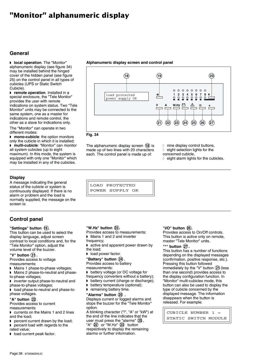
◗local operation. The "Monitor" alphanumeric display (see figure 34) may be installed behind the hinged cover of the hidden panel (see figure 25) on the control panel in all types of cubicles (UPS or Static Switch Cubicle).
◗remote operation. Installed in a special enclosure, the "Tele Monitor" provides the user with remote indications on system status. Two "Tele Monitor" units may be connected to the same system, one as a master for indications and remote control, the other as a slave for indications only.
The "Monitor" can operate in two different modes:
◗
◗
Alphanumeric display screen and control panel
18 | 19 |
|
|
|
|
|
|
| 20 |
load protected |
|
| 1 2 | 3 | 4 | 5 | 6 | 7 | 8 |
power supply OK |
|
|
|
|
|
|
|
|
|
| V | A | W.Hz | + – |
| ! |
|
| * |
|
|
|
|
| |||||
|
|
|
|
|
| ||||
|
|
|
|
|
|
|
|
| |
| 21 | 22 | 23 | 24 | 25 | 26 | 27 | ||
Fig. 34
The alphanumeric display screen 18 is | ◗ nine display control buttons, | |
made up of two lines with 20 characters | ◗ | eight selection lights for the |
each. The control panel is made up of: | concerned cubicle, | |
| ◗ | eight alarm lights for the cubicles. |
Display
A message indicating the general status of the cubicle or system is continuously displayed. If there is no alarm or problem and the load is normally supplied, the message on the screen is:
LOAD PROTECTED
POWER SUPPLY OK
Control panel
"Settings" button 19 .
This button can be used to select the display language, adjust screen contrast to local conditions and, for the "Tele Monitor" option, adjust the volume level of the buzzer.
"V" button 21 .
Provides access to voltage measurements:
◗Mains 1
◗Mains 2
◗inverter output
◗load
"A" button 22 .
Provides access to current measurements:
◗currents on the Mains 1 and 2 lines and the load;
◗percent current drawn by the load;
◗percent load with regards to the rated value;
◗load current peak factor.
"W.Hz" button 23 .
Provides access to measurements:
◗Mains 1 and 2 and inverter frequency;
◗active and apparent power drawn by the load;
◗load power factor.
"Battery" button 24 . Provides access to battery measurements:
◗battery voltage (or DC voltage for frequency converters without a battery);
◗battery current (charge or discharge);
◗battery temperature (optional);
◗remaining battery time.
"Alarms" button 25 .
Displays current or logged alarms and stops the buzzer for the "Tele Monitor" option.
A blinking character ("!", "A" or "kW") at the end of the line indicates that the user must press the "alarms" 25 ,
"A" 22 or "W.Hz" 23 button respectively to display the remaining alarms or further information.
"I/O" button 26 .
Provides access to On/Off controls. This button is active only on remote, master "Tele Monitor" units.
"*" button 27 .
This button has a number of functions depending on the displayed messages (confirmation, positive response, etc.). Pressing this button followed immediately by the "V" button 21 (less than one second) provides access to the display configuration function. In "Monitor"
CUBICLE NUMBER 1 =
STATIC SWITCH MODULE
Page 36 - 6739380EN/JC
