Introduction (cont.)
Frequency converters without redundancy
◗ in the event of a shutdown, the load |
is no longer supplied with power; |
◗ in the event of a major transient |
overload (greater than 160% of the |
rated load), the inverters will current |
limit to 160% of their rated current for 1 |
second before stopping; |
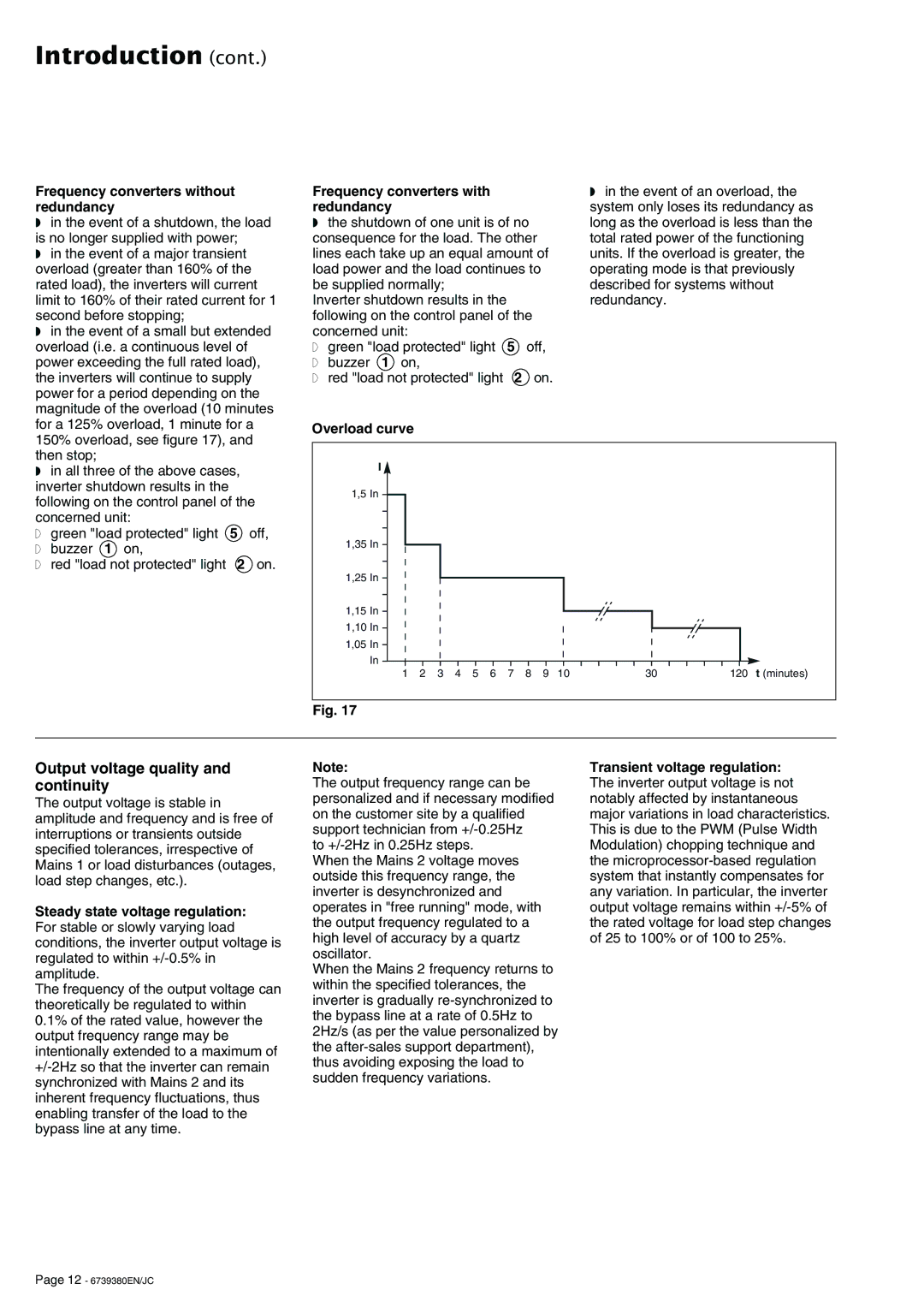
◗ in the event of a small but extended |
overload (i.e. a continuous level of |
power exceeding the full rated load), |
the inverters will continue to supply |
power for a period depending on the |
magnitude of the overload (10 minutes |
Frequency converters with redundancy
◗the shutdown of one unit is of no consequence for the load. The other lines each take up an equal amount of load power and the load continues to be supplied normally;
Inverter shutdown results in the following on the control panel of the concerned unit:
◗ green "load protected" light 5 off,
◗buzzer 1 on,
◗red "load not protected" light 2 on.
◗in the event of an overload, the system only loses its redundancy as long as the overload is less than the total rated power of the functioning units. If the overload is greater, the operating mode is that previously described for systems without redundancy.
for a 125% overload, 1 minute for a |
150% overload, see figure 17), and |
then stop; |
◗ in all three of the above cases, |
inverter shutdown results in the |
following on the control panel of the |
concerned unit: |
◗ green "load protected" light 5 off,
◗buzzer 1 on,
◗red "load not protected" light 2 on.
Overload curve |
|
|
|
|
|
|
|
|
|
|
|
| |
| I |
|
|
|
|
|
|
|
|
|
|
|
|
1,5 | In |
|
|
|
|
|
|
|
|
|
|
|
|
1,35 | In |
|
|
|
|
|
|
|
|
|
|
|
|
1,25 | In |
|
|
|
|
|
|
|
|
|
|
|
|
1,15 | In |
|
|
|
|
|
|
|
|
|
|
|
|
1,10 | In |
|
|
|
|
|
|
|
|
|
|
|
|
1,05 | In |
|
|
|
|
|
|
|
|
|
|
|
|
| In |
|
|
|
|
|
|
|
|
|
|
|
|
| 1 | 2 | 3 | 4 | 5 | 6 | 7 | 8 | 9 | 10 | 30 | 120 | t (minutes) |
Fig. 17
Output voltage quality and continuity
The output voltage is stable in amplitude and frequency and is free of interruptions or transients outside specified tolerances, irrespective of Mains 1 or load disturbances (outages, load step changes, etc.).
Steady state voltage regulation: For stable or slowly varying load conditions, the inverter output voltage is regulated to within
The frequency of the output voltage can theoretically be regulated to within
0.1% of the rated value, however the output frequency range may be intentionally extended to a maximum of
Note:
The output frequency range can be personalized and if necessary modified on the customer site by a qualified support technician from
to
When the Mains 2 voltage moves outside this frequency range, the inverter is desynchronized and operates in "free running" mode, with the output frequency regulated to a high level of accuracy by a quartz oscillator.
When the Mains 2 frequency returns to within the specified tolerances, the inverter is gradually
Transient voltage regulation: The inverter output voltage is not notably affected by instantaneous major variations in load characteristics. This is due to the PWM (Pulse Width Modulation) chopping technique and the
Page 12 - 6739380EN/JC