"Monitor" alphanumeric display (cont.)
UPS IMPOSED
TRANSFER DISABLE !
Cannot transfer the load to Main 2 due to:
◗transfer conditions not satisfied;
◗UPS operating on an independent frequency;
◗UPS operating with current limitation;
◗internal fault;
◗auxiliary control inhibits switching to Mains 2.
Measurement system
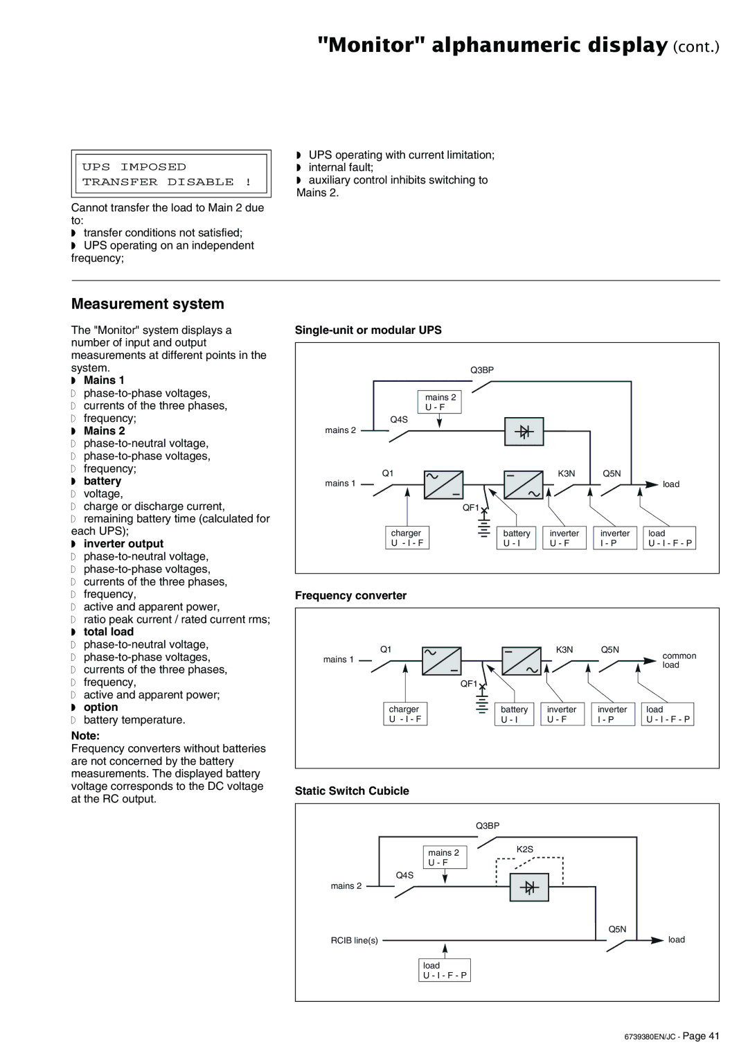
The "Monitor" system displays a number of input and output measurements at different points in the system.
◗Mains 1
◗
◗currents of the three phases,
◗frequency;
◗Mains 2
◗
◗
◗frequency;
◗battery
◗voltage,
◗charge or discharge current,
◗remaining battery time (calculated for each UPS);
◗inverter output
◗
◗
◗currents of the three phases,
◗frequency,
◗active and apparent power,
◗ratio peak current / rated current rms;
◗total load
◗
◗
◗currents of the three phases,
◗frequency,
◗active and apparent power;
◗option
◗battery temperature.
Note:
Frequency converters without batteries are not concerned by the battery measurements. The displayed battery voltage corresponds to the DC voltage at the RC output.
| Q3BP |
|
|
|
| mains 2 |
|
|
|
| U - F |
|
|
|
Q4S |
|
|
|
|
mains 2 |
|
|
|
|
Q1 |
| K3N | Q5N |
|
mains 1 |
|
|
| load |
| QF1 |
|
|
|
charger | battery | inverter | inverter | load |
U - I - F | U - I | U - F | I - P | U - I - F - P |
Frequency converter
Q1 |
| K3N | Q5N | common |
mains 1 |
|
|
| |
|
|
| load | |
|
|
|
| |
| QF1 |
|
|
|
charger | battery | inverter | inverter | load |
U - I - F | U - I | U - F | I - P | U - I - F - P |
Static Switch Cubicle
mains 2 U - F
Q4S
mains 2
RCIB line(s)
load
U - I - F - P
Q3BP
K2S
Q5N
load
6739380EN/JC - Page 41
