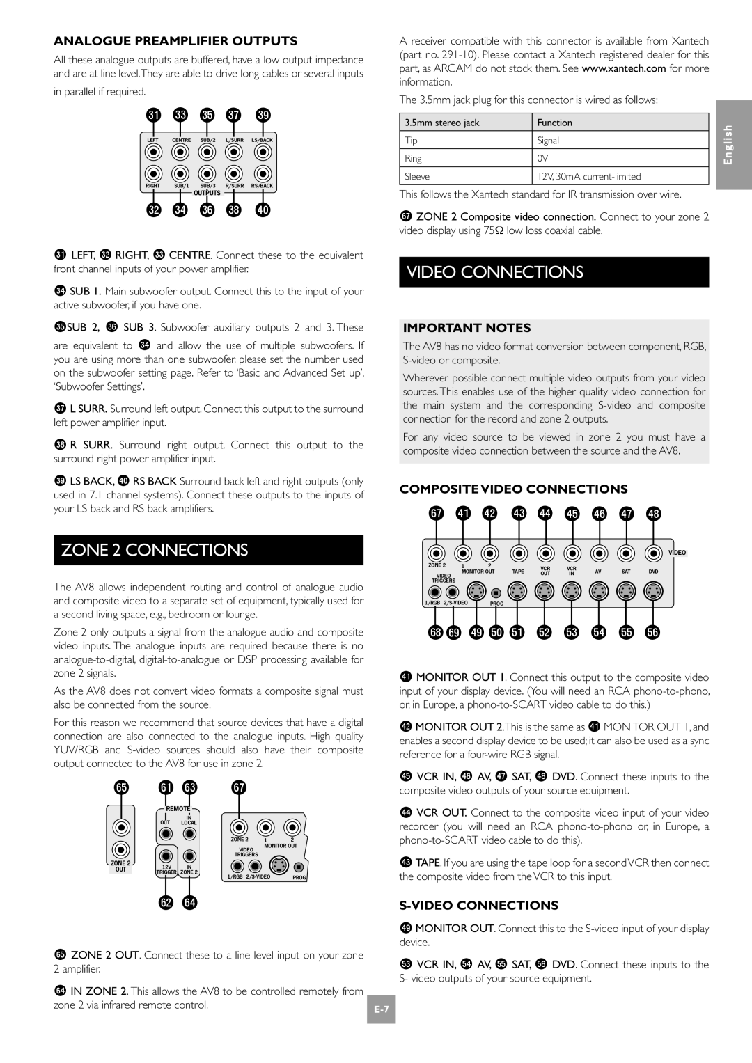
ANALOGUE PREAMPLIFIER OUTPUTS
All these analogue outputs are buffered, have a low output impedance and are at line level.They are able to drive long cables or several inputs
in parallel if required.
dl dn dp dr dt
LEFT CENTRE SUB/2 L/SURR LS/BACK
RIGHT SUB/1 SUB/3 R/SURR RS/BACK
OUTPUTS
dm do dq ds ek
dl LEFT, dm RIGHT, dn CENTRE. Connect these to the equivalent front channel inputs of your power amplifier.
do SUB 1. Main subwoofer output. Connect this to the input of your active subwoofer, if you have one.
dpSUB 2, dq SUB 3. Subwoofer auxiliary outputs 2 and 3. These
are equivalent to do and allow the use of multiple subwoofers. If you are using more than one subwoofer, please set the number used on the subwoofer setting page. Refer to ‘Basic and Advanced Set up’, ‘Subwoofer Settings’.
dr L SURR. Surround left output. Connect this output to the surround left power amplifier input.
ds R SURR. Surround right output. Connect this output to the surround right power amplifier input.
dt LS BACK, ek RS BACK Surround back left and right outputs (only used in 7.1 channel systems). Connect these outputs to the inputs of your LS back and RS back amplifiers.
ZONE 2 CONNECTIONS
The AV8 allows independent routing and control of analogue audio and composite video to a separate set of equipment, typically used for a second living space, e.g., bedroom or lounge.
Zone 2 only outputs a signal from the analogue audio and composite video inputs. The analogue inputs are required because there is no
As the AV8 does not convert video formats a composite signal must also be connected from the source.
For this reason we recommend that source devices that have a digital connection are also connected to the analogue inputs. High quality YUV/RGB and
gp | gl gn | gr |
|
| |
| REMOTE |
|
|
| |
| OUT | IN |
|
|
|
| LOCAL |
|
|
| |
|
|
| ZONE 2 | 1 | 2 |
|
|
| VIDEO | MONITOR OUT | |
|
|
|
|
| |
|
|
| TRIGGERS |
|
|
ZONE 2 | 12V | IN |
|
|
|
OUT |
|
|
| ||
| TRIGGER | ZONE 2 | 1/RGB | PROG | |
|
|
| |||
gm go
gp ZONE 2 OUT. Connect these to a line level input on your zone |
|
2 amplifier. |
|
go IN ZONE 2. This allows the AV8 to be controlled remotely from |
|
zone 2 via infrared remote control. | |
|
A receiver compatible with this connector is available from Xantech (part no.
The 3.5mm jack plug for this connector is wired as follows:
3.5mm stereo jack | Function |
|
|
Tip | Signal |
|
|
Ring | 0V |
|
|
Sleeve | 12V, 30mA |
|
|
This follows the Xantech standard for IR transmission over wire.
gr ZONE 2 Composite video connection. Connect to your zone 2 video display using 75Ω low loss coaxial cable.
VIDEO CONNECTIONS
IMPORTANT NOTES
The AV8 has no video format conversion between component, RGB,
Wherever possible connect multiple video outputs from your video sources. This enables use of the higher quality video connection for the main system and the corresponding
For any video source to be viewed in zone 2 you must have a composite video connection between the source and the AV8.
COMPOSITE VIDEO CONNECTIONS
gr el em en eo ep eq er es
VIDEO
ZONE 2 | 1 | 2 |
| VCR | VCR |
|
|
| |
| MONITOR OUT | TAPE | AV | SAT | DVD | ||||
VIDEO | OUT | IN | |||||||
|
|
|
|
|
| ||||
TRIGGERS |
|
|
|
|
|
|
|
| |
1/RGB | PROG |
|
|
|
|
|
| ||
gsgt etfk fl fm fn fo fp fq
el MONITOR OUT 1. Connect this output to the composite video input of your display device. (You will need an RCA
em MONITOR OUT 2.This is the same as el MONITOR OUT 1, and enables a second display device to be used; it can also be used as a sync reference for a
ep VCR IN, eq AV, er SAT, es DVD. Connect these inputs to the composite video outputs of your source equipment.
eo VCR OUT. Connect to the composite video input of your video recorder (you will need an RCA
en TAPE. If you are using the tape loop for a secondVCR then connect the composite video from the VCR to this input.
S-VIDEO CONNECTIONS
et MONITOR OUT. Connect this to the
fn VCR IN, fo AV, fp SAT, fq DVD. Connect these inputs to the S- video outputs of your source equipment.
English