REQUIRED STEPS AFTER FINAL PLACEMENT SECURING UNIT TO STRUCTURE
The compressor is secured to the base with two (2) bolts for shipping. Although the unit will perform as designed with the shipping bolts in place, there may be a noticeable additional noise and vibration noted. To obtain the lowest noise and vibration levels, remove the shipping bolts after the unit is in its final operating location. To gain access to the compressor, the compressor access panel must be removed (Figure 9). Once this panel is removed, the CRV/ERV air duct must be removed. See Figure 6.
The air duct is removed by pulling it straight toward you; there are no screws securing it in place. Both the top and bottom slide toward you at the same time (pull hard). Once removed, the compressor is visible as well as the tags on the shipping bolts (Figure 5).
After the compressor shipping bolts have been removed, the CRV/ERV air duct can be slid back in place and the compressor access panel attached.
MINIMUM INSTALLATION HEIGHT
The minimum installation height to the bottom of the roof or fixed ceiling for ducted applications is 9 ft. 7 in. This provides enough clearance to install the duct work. See Figure 7A.
The IWS Series wall sleeve has a
Several construction options are available for unit installation of the IZ Series. Serviceability and filter access must be considered before installing. See Figure 5D for required clearances and recommended service access dimensions.![]()
Shipped with the
Additional/optional mounting holes for up to a 3/8" diameter fastener are also available in the backside of the unit. These can be accessed by:
•removing the air filters for the uppermost set
•removing the compressor section service door for the lower set
Refer to WOOD FRAMED INSTALLATION for additional framing required to secure unit to wall.
The additional/optional mounting holes will require a long extension to drive the fasteners.
SEISMIC CONSIDERATIONS
The
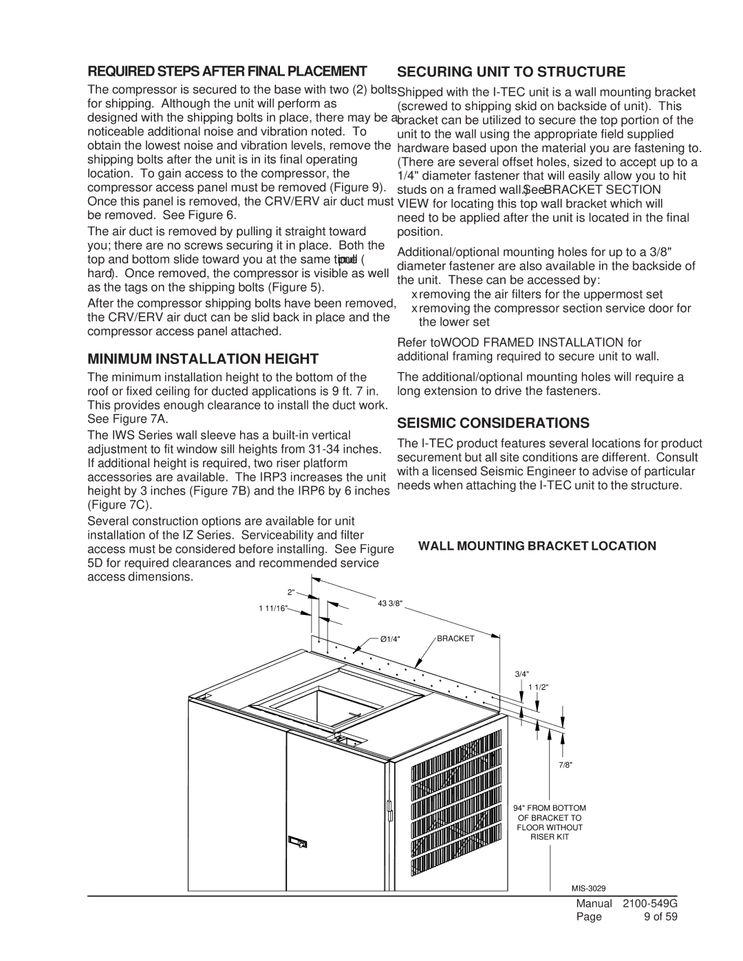
WALL MOUNTING BRACKET LOCATION
| 2" |
1 11/16" | 43 3/8" |
|
![]() Ø1/4" BRACKET
Ø1/4" BRACKET
3/4"
1 1/2"
7/8"
94" FROM BOTTOM OF BRACKET TO FLOOR WITHOUT RISER KIT
Manual | |
Page | 9 of 59 |