DS72 HOST MODULE OWNER’S MANUAL
CABLING
CABLING
RJ-45 CABLES AND ADAPTERS
IMPORTANT: The DS72 network interface module has an
CAUTION: All power should be removed from the DS72 unit prior to removing or installing cables.
The DS72 Ethernet connection requires a straight cable between the ethernet port of the DS72 module and the network hub. The “LINK” light will light green when a good link has been established.
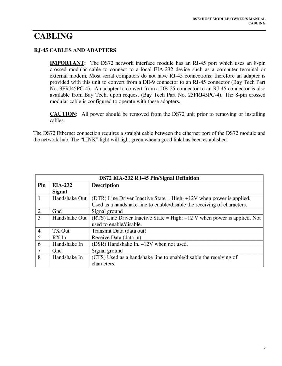
|
| DS72 |
Pin |
| Description |
| Signal |
|
1 | Handshake Out | (DTR) Line Driver Inactive State = High: +12V when power is applied. |
|
| Used as a handshake line to enable/disable the receiving of characters. |
2 | Gnd | Signal ground |
3 | Handshake Out | (RTS) Line Driver Inactive State = High: +12 V when power is applied. Not |
|
| used to enable/disable. |
4 | TX Out | Transmit Data (data out) |
5 | RX In | Receive Data (data in) |
6 | Handshake In | (DSR) Handshake In. |
7 | Gnd | Signal ground |
8 | Handshake In | (CTS) Used as a handshake line to enable/disable the receiving of |
|
| characters. |
6