INSTALLATION
Connecting Multiple Switches (Daisy-Chaining)
You can daisy-chain up to 16 Switches and Expanders together; this will give a server administrator control over a maximum of 256 computers. In addition, when a second Switch is daisy-chained, additional consoles can be added, creating a configuration of up to four consoles. Each daisy-chained group of Switches becomes a unit that is referred to as a “BANK” and assigned an address. The Switch that the console (keyboard, mouse, and monitor) is connected to is referred to as a “primary” switch. BANKs 00 and 01 can be configured as primary console switches, allowing up to four consoles. BANKs 02 through 15 can only be configured as secondary Switches (without console support). If BANKs 00 through 01 do not have a console attached, they function as secondary Switches. However, the connections on these BANKs are hot swappable. For example, if a console is added to one of the first two BANKs, it will immediately become a primary console Switch.
Note: A Daisy-Chain Cable (F1D9402-XX) is required to daisy-chain each ENTERPRISE Quad-Bus Series KVM Switch and is available through your Belkin reseller or online at belkin.com.
All OmniView ENTERPRISE Quad-Bus Series KVM Switches feature a “BANK DIP” switch. The BANK DIP switch is used for proper identification of the Switch.
•For a single-unit configuration, set the BANK DIP switch on the Switch to the “standalone” (BANK address 00) setting. This is the factory default setting.
•For multi-unit configuration, the BANK DIP switch on the primary units must be set to BANK address 00 to (or) 01. Secondary units must be set to a unique BANK address (from 02 through 15). Refer to the chart below for DIP switch settings.
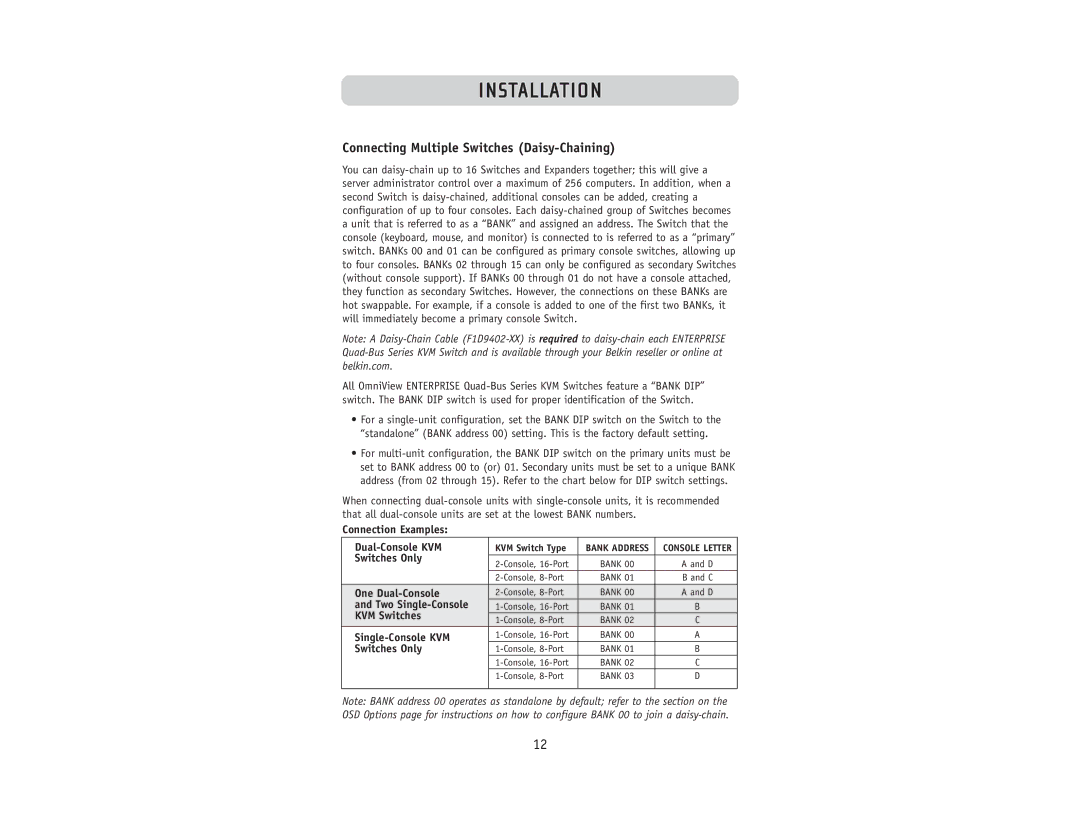
When connecting dual-console units with single-console units, it is recommended that all dual-console units are set at the lowest BANK numbers.
Connection Examples:
| Dual-Console KVM | KVM Switch Type | BANK ADDRESS | CONSOLE LETTER |
| Switches Only | | | |
| 2-Console, 16-Port | BANK 00 | A and D |
| |
| | 2-Console, 8-Port | BANK 01 | B and C |
| One Dual-Console | 2-Console, 8-Port | BANK 00 | A and D |
| and Two Single-Console | 1-Console, 16-Port | BANK 01 | B |
| KVM Switches | 1-Console, 8-Port | BANK 02 | C |
| Single-Console KVM | 1-Console, 16-Port | BANK 00 | A |
| Switches Only | 1-Console, 8-Port | BANK 01 | B |
| | 1-Console, 16-Port | BANK 02 | C |
| | 1-Console, 8-Port | BANK 03 | D |
| | | | |
Note: BANK address 00 operates as standalone by default; refer to the section on the OSD Options page for instructions on how to configure BANK 00 to join a daisy-chain.