INSTALLATION
Connecting the Daisy-Chain Cable:
5.Begin with BANK 00. Using the
6.Connect the other end of the
Note: It does not matter which unit is the primary unit, only that they are connected
Adding Additional Units:
7.Continuing in the same manner, using the
CAUTION: Never connect
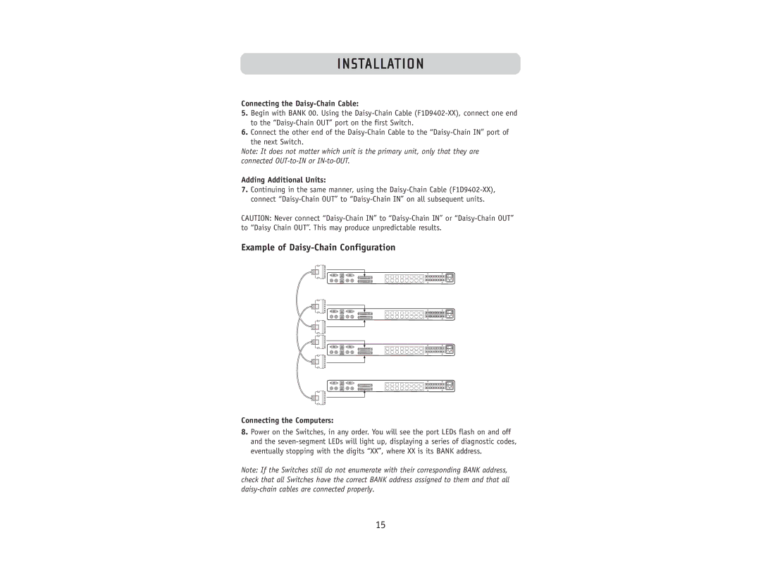
Example of Daisy-Chain Configuration
Connecting the Computers:
8.Power on the Switches, in any order. You will see the port LEDs flash on and off and the
Note: If the Switches still do not enumerate with their corresponding BANK address, check that all Switches have the correct BANK address assigned to them and that all
15