Black Box®LB1350A/LB1351A
7 - PARTS IDENTIFICATION
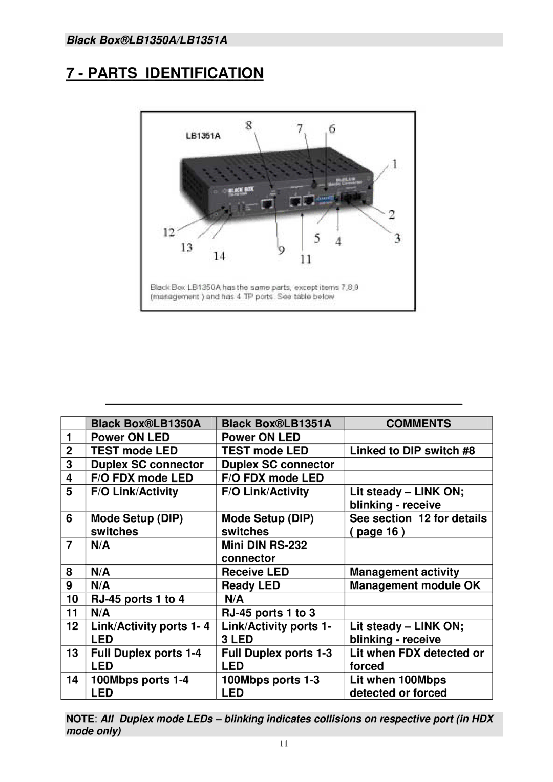
| Black Box®LB1350A | Black Box®LB1351A | COMMENTS |
1 | Power ON LED | Power ON LED |
|
2 | TEST mode LED | TEST mode LED | Linked to DIP switch #8 |
3 | Duplex SC connector | Duplex SC connector |
|
4 | F/O FDX mode LED | F/O FDX mode LED |
|
5 | F/O Link/Activity | F/O Link/Activity | Lit steady – LINK ON; |
|
|
| blinking - receive |
6 | Mode Setup (DIP) | Mode Setup (DIP) | See section 12 for details |
| switches | switches | ( page 16 ) |
7 | N/A | Mini DIN |
|
|
| connector |
|
8 | N/A | Receive LED | Management activity |
9 | N/A | Ready LED | Management module OK |
10 | N/A |
| |
11 | N/A |
| |
12 | Link/Activity ports 1- 4 | Link/Activity ports 1- | Lit steady – LINK ON; |
| LED | 3 LED | blinking - receive |
13 | Full Duplex ports | Full Duplex ports | Lit when FDX detected or |
| LED | LED | forced |
14 | 100Mbps ports | 100Mbps ports | Lit when 100Mbps |
| LED | LED | detected or forced |
NOTE: All Duplex mode LEDs – blinking indicates collisions on respective port (in HDX mode only)
11