Black Box®LB1350A/LB1351A
12 – CONFIGURATION SWITCHES
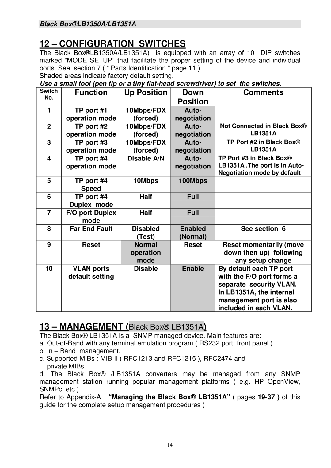
The Black Box®LB1350A/LB1351A) is equipped with an array of 10 DIP switches marked “MODE SETUP” that facilitate the proper setting of the device and individual ports. See section 7 ( “ Parts Identification ” page 11 )
Shaded areas indicate factory default setting.
Use a small tool (pen tip or a tiny
Switch | Function | Up Position | Down | Comments |
No. |
|
| Position |
|
|
|
|
| |
1 | TP port #1 | 10Mbps/FDX | Auto- |
|
| operation mode | (forced) | negotiation |
|
2 | TP port #2 | 10Mbps/FDX | Auto- | Not Connected in Black Box® |
| operation mode | (forced) | negotiation | LB1351A |
3 | TP port #3 | 10Mbps/FDX | Auto- | TP Port #2 in Black Box® |
| operation mode | (forced) | negotiation | LB1351A |
4 | TP port #4 | Disable A/N | Auto- | TP Port #3 in Black Box® |
| operation mode |
| negotiation | LB1351A .The port is in Auto- |
|
|
|
| Negotiation mode by default |
5 | TP port #4 | 10Mbps | 100Mbps |
|
| Speed |
|
|
|
6 | TP port #4 | Half | Full |
|
| Duplex mode |
|
|
|
7 | F/O port Duplex | Half | Full |
|
| mode |
|
|
|
8 | Far End Fault | Disabled | Enabled | See section 6 |
|
| (Test) | (Normal) |
|
9 | Reset | Normal | Reset | Reset momentarily (move |
|
| operation |
| down then up) following |
|
| mode |
| any setup change |
10 | VLAN ports | Disable | Enable | By default each TP port |
| default setting |
|
| with the F/O port forms a |
|
|
|
| separate security VLAN. |
|
|
|
| In LB1351A, the internal |
|
|
|
| management port is also |
|
|
|
| included in each VLAN. |
13 – MANAGEMENT (Black Box® LB1351A)
The Black Box® LB1351A is a SNMP managed device. Main features are:
a.
c. Supported MIBs : MIB II ( RFC1213 and RFC1215 ), RFC2474 and private MIBs.
d. The Black Box® /LB1351A converters may be managed from any SNMP management station running popular management platforms ( e.g. HP OpenView, SNMPc, etc )
Refer to
14
