27
MUTLILINK FRAME RELAY
27.1Multilink Frame Relay FRF.15 and FRF.16
Multilink Frame Relay (MFR) is actually composed of two standards: FRF.15 and FRF.16. The latter is more common and defines UNI/NNI interfaces for implementing MFR. FRF.16 is used for multiplexing dedicated T1s in the local loop and requires compatible equipment at the carrier POP. FRF.15, or
27.1.1 Features
Low cost way of providing added bandwidth to private networks
Can be done without the knowledge of the Frame Relay provider
Scalable bandwidth using MFR for customers based on T1 access
Traffic can be routed or switched using Frame Relay at the end points
A customer desiring to implement
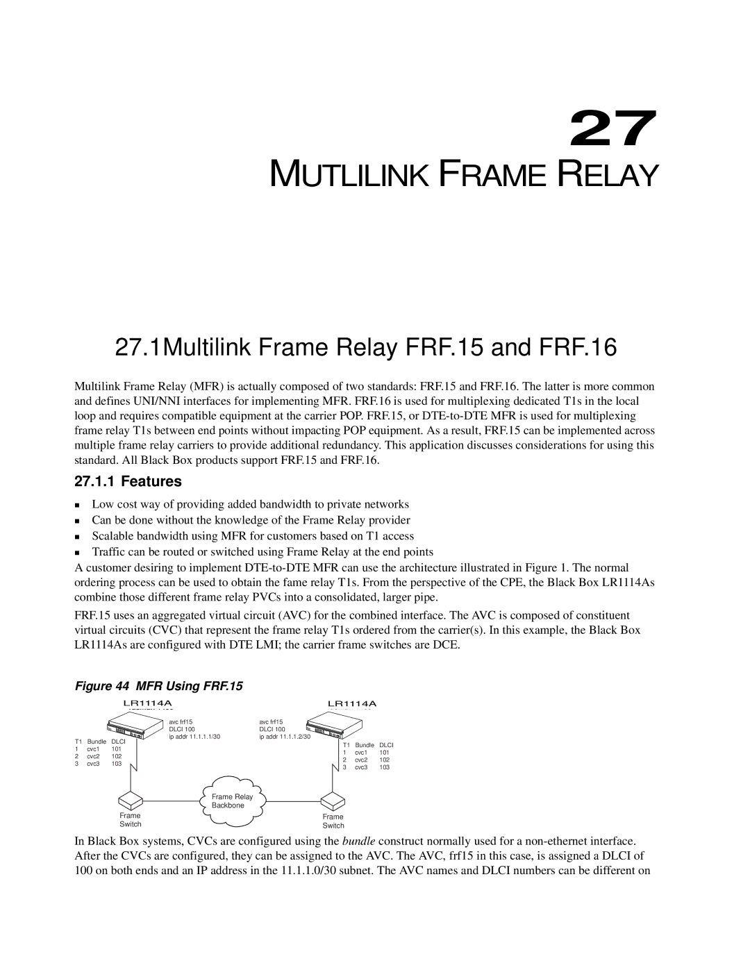
FRF.15 uses an aggregated virtual circuit (AVC) for the combined interface. The AVC is composed of constituent virtual circuits (CVC) that represent the frame relay T1s ordered from the carrier(s). In this example, the Black Box LR1114As are configured with DTE LMI; the carrier frame switches are DCE.
Figure 44 MFR Using FRF.15
LR1114A | LR1114A |
T1 | Bundle | DLCI |
1 | cvc1 | 101 |
2 | cvc2 | 102 |
3 | cvc3 | 103 |
avc frf15 | avc frf15 |
DLCI 100 | DLCI 100 |
ip addr 11.1.1.1/30 | ip addr 11.1.1.2/30 |
T1 | Bundle | DLCI |
1 | cvc1 | 101 |
2 | cvc2 | 102 |
3 | cvc3 | 103 |
Frame Relay
Backbone
Frame | Frame |
Switch | Switch |
In Black Box systems, CVCs are configured using the bundle construct normally used for a
