Black Box LR11xx Series Router Configurations Guide
Black Box1/configure/crypto/> exit
Black Box1/configure> snmp
Black Box1/configure/snmp> community public rw
Black Box1/configure/snmp> exit
Step 12: Display SNMP communities
Blackbox>show snmp communities
Community = public, privileges=rw
Blackbox>
Step 13: Repeat steps 1 - 10 with suitable modifications on Black Box2 prior to managing Black Box1 from Black Box2’s LAN side
Step 14: Test the IPSec tunnel for managing the Black Box1 router from a host on Black Box2’s LAN.
Step 15: When the SNMP manager starts managing Black Box1 from Black Box2’s LAN, display the IKE and IPSec SA tables using:
show crypto ike sa all
show crypto ike sa all detail show crypto ipsec sa all
show crypto ipsec sa all detail
4.3Example 2: Single Proposal: Tunnel Mode Between Two Black Box Security Gateways
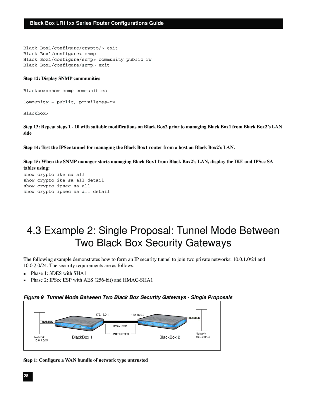
The following example demonstrates how to form an IP security tunnel to join two private networks: 10.0.1.0/24 and 10.0.2.0/24. The security requirements are as follows:
Phase 1: 3DES with SHA1
Phase 2: IPSec ESP with AES
Figure 9 Tunnel Mode Between Two Black Box Security Gateways - Single Proposals
| 172.16.0.1 | 172.16.0.2 | TRUSTED |
|
|
| |
TRUSTED |
|
|
|
| IPSec ESP |
|
|
| UNTRUSTED | BlackBox 2 | Network |
Network | BlackBox 1 | 10.0.2.0/24 | |
10.0.1.0/24 |
|
|
|
Step 1: Configure a WAN bundle of network type untrusted
28