28
CONFIGURING FRAME RELAY AND
MULTILINK FRAME RELAY
28.1Layer Two Configurations FR and MFR
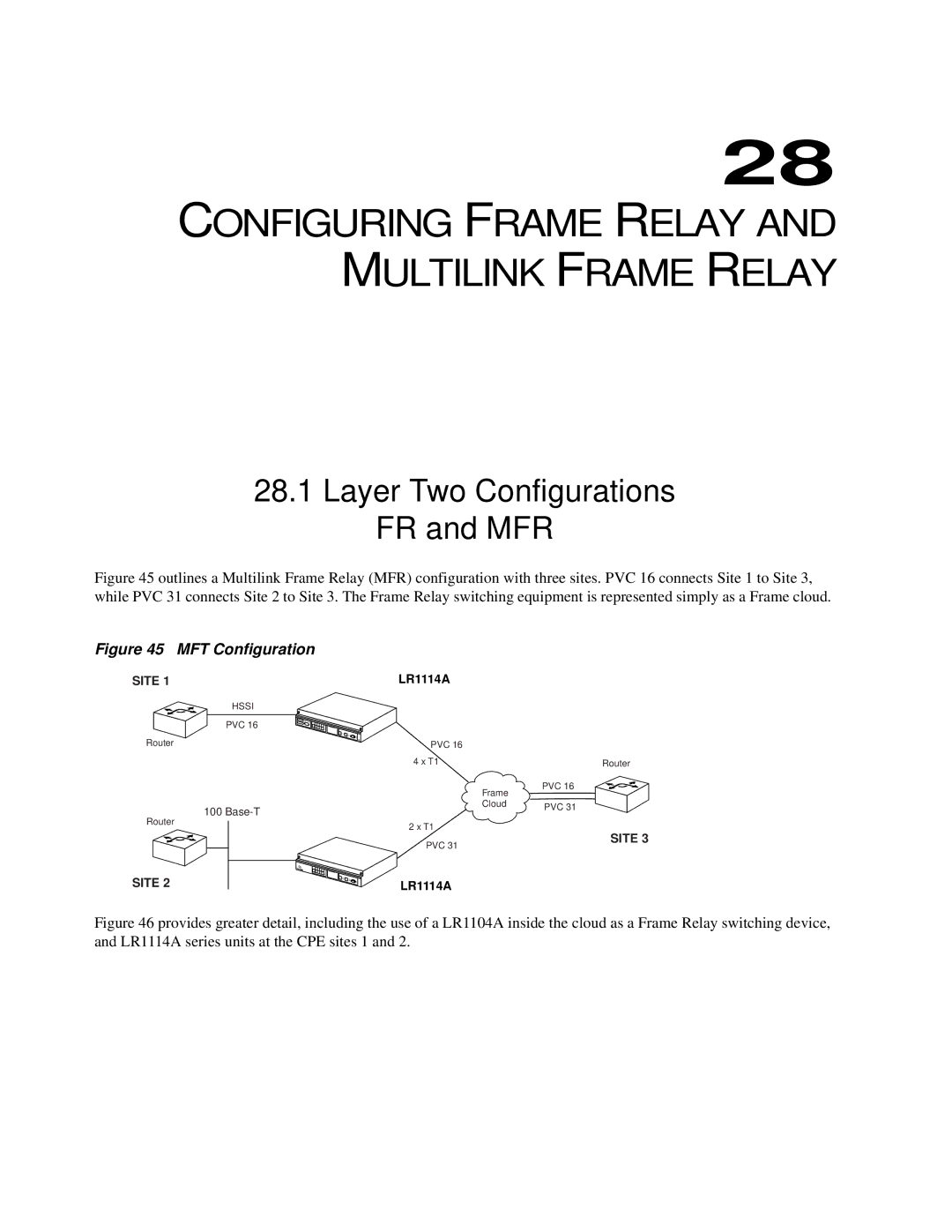
Figure 45 outlines a Multilink Frame Relay (MFR) configuration with three sites. PVC 16 connects Site 1 to Site 3, while PVC 31 connects Site 2 to Site 3. The Frame Relay switching equipment is represented simply as a Frame cloud.
Figure 45 | MFT Configuration |
|
|
SITE 1 | LR1114A |
|
|
| HSSI |
|
|
| PVC 16 |
|
|
Router | PVC 16 |
|
|
| 4 x T1 |
| Router |
|
| Frame | PVC 16 |
|
|
| |
| 100 | Cloud | PVC 31 |
|
| ||
|
|
|
Router
2 x T1
PVC 31
SITE 3
SITE 2
LR1114A