Comsphere 3800PLUS Modems
Trademarks
Warranty, Sales, and Service Information
Users Guide
3980-A2-GB30-20
Important Safety Instructions
United States
Government Requirements and Equipment Return
Government Requirements
Canada
Table of Contents
Call Setup Branch
Fax Operation
Optional SDCP, 3811Plus Faceplate, and Optional SDU
List of Figures
List of Tables
Technical Specifications for Comsphere 3800 Plus Modems
Preface
How to Use This Manual
Objectives and Reader Assumptions
Related Documents
Introduction
Features
Overview
Comsphere Models
Options
3810Plus and 3820Plus Modem Package
3810Plus and 3820Plus Installation
Customer-Supplied Equipment
3810Plus and 3820Plus Modem Installation
Plus Rear Panel
DTE Connection
Dial-Line Connection
3810Plus 4-Wire/2-Wire Leased-Line Network Connection
AC Power Supply Connection
3820Plus 2-Wire Leased-Line Network Connection
Network Management System Connection
Hubbing Device
Power On Selftst Passed
Modem Power-Up
Removing and Replacing 3810Plus and 3820Plus Modems
3811Plus Modem Package
3811Plus Installation
Plus Modem
3811Plus Modem Installation
Installing a 3811Plus Modem
Removing and Replacing 3811Plus Modems
Front Panel Operation
Diagnostic Control Panels
3810Plus and 3820Plus DCP
3811Plus Faceplate and Shared Diagnostic Control Panel Sdcp
Status Indicators
Label Color Indicates
3800Plus DCP LEDs
DCP Operation
Idle28.8 CallSetup
LCD Display
Sdcp LEDs Label Color Indicates
Keypad
Left/Right Scroll Indicator
Menu Structure
Top-Level Menu Status Operational Messages
Alarm Status Indicates
Top Level Menu Status
Normal Operation Indicates
Call Failure Indicates
Normal Call Indicates
Call Disconnect Indicates Messages
AT Command Indicates
Dial Backup Indicates
Firmware Download Indicates Result Messages
Dial Access Indicates Security Messages
Dial Access Security Messages
Common Operational Messages
Common Indicates
Using the Diagnostic Control Panel DCP
Selecting Factory Configuration Options
Type AT
Frnt Panl Acces Grant Deny
Diagnostic Control Panel Security Access
Call Setup Branch
Dial
Call Setup Branch
Disconnect
Call Setup Answer
Disconnect Answer Command Complete
Answer
Dial Standby/Return to Dial
Call Setup ReturntoDial
Call Setup Dial Standby
Dial Standby Command Complete
Change Directory
01 5551234 ← Nxt
Call Setup ChangeDirectory
02 z
02 9 z
Valid Dial Command Modifier
Status Branch
Status Branch
Idle StatusTest
RevLev
SigQual
Sig/Noise
NearEcho
Status Identity Ser # =
Identity
Record
Options
Record Status Display Clear
Status Options Record
Record Number Modem O.K
Test Branch
Abort
Test Branch
Self
Test LocAnalogLoop
Loc Analog Loop
Test Local Loop Started
Test RemDigitalLoop
Rem Digital Loop
Test Remote Loop Started
Test LocDigitalLoop
Loc Digital Loop
Test Digitl Loop Started
Pattern Test and Local Analog Loopback Test
Pattern
Test Pattern Blks Errd =
Test Pattern
Configure Branch
DCP Configuration Process
AT Command Configuration Process
Configure Branch
Editing and Saving a Configuration Option
Sav EditArea to Active Saved
Summary
DTE Interface Configuration Options
Configuration Tables
Async/Sync Mode Async Nxt Async Sync
DTE Interface
Asyn Parity Bit None Nxt None Even Odd Mark Space
Async #Data Bits Nxt 8 7 9DirectMde 6DirectMde
Asyn #Stop Bits Nxt 1
DTE Interface Configuration Options
DTE Interface Configuration Options
RTS Action Ignore Nxt Ignore StndrdRS232 SimCntlCar CntlCar
RTS/CTS Delay 0 msec Nxt 0msec 10msec 50msec 150msec 600msec
DTE Rate=VF Disable End Disable Enable
CT111Rate Cntl Disable Nxt Disable Fallback1 Fallback2
TX Clock Source Internal Nxt Internal External RXCLoop
DTE Dialer
DTE Dialer Configuration Options
CommandCharEcho Enable Nxt EnableDisable
BreakForceEscap Disable Nxt Disable Enable
AT Escape Char 043 Asci Nxt 043 Asci
CarriageRtn Char 013 Asci Nxt ↑ 013 Asci
Backspace Char 008 Asci Nxt ↑ 008 Asci
Result Codes Enable Nxt Enable Disable EnableInOrig
Linefeed Char 010 Asci Nxt ↑ 010 Asci
ResultCode Form Words Nxt Words Numbers 1 Numbers
AT Cmnd Mode Normal Nxt Normal NoERROR NoStrapOrERR
V25bis Coding Ascii Nxt Ascii Ebcdic
V25bis IdleFill Mark Nxt Mark Flag
DTR Cont Repeat Disable End Disable Enable
25b NewLineChr CR+LF Nxt CR+LF CR LF
Line Dialer
Line Dialer Configuration Options
Fast Disconnect Disable Nxt Disable Enable
BusyTone Detect Enable Nxt Enable Disable
``,º Pause Time 2sec Nxt 2sec 4sec 6sec 8sec 10sec 20sec
NoAnswer Timout 45sec Nxt 45sec 30sec 60sec 120sec
No Carrier Disc 2sec Nxt 2sec 5sec Disable 10sec 20sec
Long Space Disc Enable Nxt Enable Disable
No Data Disc Disable Nxt Disable 10min 30min 60min
Auto Make Busy Disable Nxt Disable Enable
MI/MIC Dialing Disable End Disable Enable
MakeBusyViaDTR Disable Nxt Disable Enable
Dial Line
Dial Line Configuration Options
Modulation Nxt V34 V32bis/terbo V21/V22/BELL
Dial LineRate Nxt 28800V34 33600 31200 26400V34 21600V34
Autorate Enable Nxt Enable Disable StartAt48 StartAt96
Automode Enable Nxt Enable Disable System
Train Time Long Nxt Long Short
V22b Guard Tone Disable Nxt Disable 550Hz 1800Hz
FallFwdDelay Disable End Disable 5mins 15mins 1hour
Dial Line Configuration Options Asymmetric Rate Enable
Leased Line
Leased Line Configuration Options
Modulation Nxt V34 V32bis/terbo V22bis V29/V33
Autorate Enable Nxt Enable Disable
Leased Line Configuration Options
CarrierOn Level ± 43dbm End ± 43dbm ±26dbm
FallFwdDelay Disable
42/MNP/Buffer
42/MNP/Buffer Configuration Options
MNP5 Compress Enable Nxt Enable Disable
V42bis Compress Enable Nxt Enable Disable
EC Negotiat Bfr Disable Nxt Disable Enable Disab&Switch
Flw Cntl of Mdm Disable Nxt Disable XON/XOFF RTStoMdm
Flw Cntl of DTE CTStoDTE Nxt CTStoDTE Disable XON/XOFF
EC Fallbck Char 013 Asci Nxt 013 Asci
Mdm/Mdm FlowCtl Disable Nxt Disable Enable
XON/XOFF Psthru Disable Nxt Disable Enable
Break Buffr Ctl Keep-Data Nxt Keep-Data Discard-Data
RxBuffDiscDelay Disable Nxt 10sec 60sec Disable
TXBuffDiscDelay 10sec Nxt 10sec 60sec Disable
Send Break Cntl Data-First Nxt Data-First Break-First
Max Frame Size Nxt 256 192 128 64 32
CellularEnhance Disable End Disable Enable
Test
Test Configuration Options
V54 Device Type Peripheral End Peripheral Intermediate
V54 Address Disable Nxt Disable Address Values
Misc
Miscellaneous Configuration Options
StrapsWhenDisc NoChange Nxt NoChange Reload RelodNoATChg
Speaker Control OnUntilCarr Nxt OnUntilCarr Off On
Access frm Remt Enable Nxt Enable Disable
Speaker Volume Medium Nxt Medium Low High
Dir#1Callback Disable Nxt Disable Enable
RemAccssPasswrd Nxt
CellulrRJ11Adpt Disable End Disable Enable
NMS DTR Alarm Disable Nxt Disable Enable
NetworkPosition Tributary Nxt Tributary Control
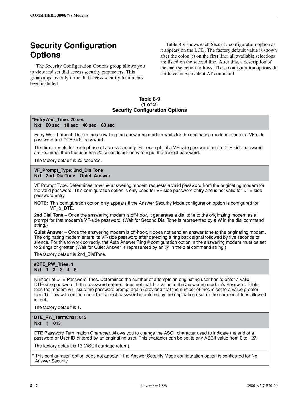
Security Configuration Options
Security Configuration Options
DTEPWBkSpChar 008 Nxt
GetUserID Disable Nxt Disable Enable
NMSReporting Nxt
AnswerSecur NoAnswSec Nxt NoAnswSec DTEOnly VF&DTE VFw/DTE
Control Branch
Control Branch
Idle Control Remote
Control Speaker Reset
Reset
Reset
Speaker
Make Busy/Remove Make Busy
Service Line/Disconnect Service Line
Control DownloadCode
Download Code
Download Code CloneRemote
AbortDownload
Password Invalid
Access Disabled
Incompat Modulat
No Response
DownldOnly Mode CallSetup
RemClone OK CallSetup
Automatic Firmware Download
Download Failure
Overview Remote Branch
Remote Branch
Online Control Remote
Remote Mode Fail ± No
Online Control ExitRem
Remote Branch
Security
Answer Access Security
Originate Access Security
ATD%abc123%T9,8005551234 press Enter
DTE-Side Passwords
Security Branch
Set Access Ctrl
Idle Control Security
Admin Password? Ent
Security SetAccessCtrl
Set Access Ctrl Edit PassWd Table
Select Index Ent
PsWdType Nxt Cleared DTE Entry VFEntry VFplusDTE
Edit Password Table Group Options
Edit PsWd Nxt yyyyyyyy or zzzzzz
Save Edit? Edit Save Yes No
Set Answer Sec NoAnswSec DTEOnly VF&DTE VFw/DTE
Set Answer Security Group Options
Set Originate Security Group Options
Set Access Ctrl SetOrigSec
Set Orig Sec NoOrigSec EnaOrigSec
Reset Security
Reset Security EraseAllPassWd
Security Password Entry Techniques
ATDT5551234W12345678# ATDP5551234T@12345678#
Database Table Examples
Originate Access Password
Type ATD%abc123%T9,8005551234
Assigned to column is not stored in the modem
Winter DTEEntry User a
11-14
Fax Operation
Fax Operation
12-2
Switching Between Data Mode and Online Command Mode
AT Command Set and 13 S-Registers
Operating Modes
AT Command List
Command Guidelines
AT Command Format
Repeat Last Command
3800Plus AT Commands Description Front Panel Branch
Answer Mode
Hook Switch Control
Command Character Echo
Dial Stored Number
Identification
Return to Online or Data Mode
Speaker Volume
Speaker On/Off
Pulse Dial
Reset and Load Active
Configuration Options
Long Space Disconnect
DTR Action
LSD Control
Option Command Value
Select Factory Default Configuration Options
22bis Guard Tone
Dial Transmit Level
Leased Mode
Dial Transmit Level Type
RTS Action
Async/Sync Mode and DTE Dialer Type
DSR Control
Tests
View Configuration Options
Write Save to Memory
Transmit Clock Source
Error Control Negotiate Buffer
Error Control Maximum Frame Size
Error Control Mode
\A3
Error Control Fallback Character
No Data Disconnect Timer
Service Class Selection
Flow Control of DTE, Flow Control of Modem
Register Format
Register List
Auto-Answer Ring Number
AT Escape Character
Line Feed Character
No Answer Timeout
Backspace Character
Blind Dial Pause
Test Timeout
Asymmetric Rate Mode
RTS-to-CTS Delay
Rate Auto Originate
Auto Redial
Receive Buffer Disconnect Delay
DTR Cont Repeat
Auto Make Busy
Train Time
Dial-Line Rate
Leased TX Level
Leased-Line Rate
Bad Lines Auto Originate
Auto Dial Standby
Transmit Buffer Disconnect Delay
Leased-Line Carrier On Level
DTE RL CT140
Remote Access Password Part
Access from Remote
Address
Device Type
25bis Idle Character
25bis Coding
25bis New Line Character
NMS Call Messages
Network Position Identification
DTR Alarm Reporting
Network Management Address
Autorate Dial Line
AT Command Mode
No Data Disconnect Trigger Signal
Autorate Leased Line
MI/MIC Dialing
ARQ Window Size Increase
Straps When Disconnected
DTE Rate=VF Rate
Cellular Enhancements
RJ11 Cellular Adapt
Train On Data
Menu Tree a
3980-A2-GB30-20
Menu Tree
Comsphere 3800Plus Modems
Table B-1 Result Codes Numbers Word Description
Result Codes B
Connect Connection at 16,800 bps
Result Codes
Symptom Action
Troubleshooting C
Table C-1
Modem Integrity
Modem ± DTE Connection
Table C-2
Modem ± VF Connection
Table C-3
Branch
Table C-4
Dial Backup Operation
Online Operation
Table C-5
Criteria
Technical Specifications D
Approvals 110 Vac, 60 Hz only
FAX Modulations
AC Power Requirements
Pin Assignments E
EIA-232-D Pin Assignments
Signal Circuit Function Source
Table E-1 EIA-232-D Pin Assignments RS-232 Pin Name
Leased
VF Connector Pin Assignments
JM8 to RJ11 Crossover Cable
Ccitt V.25bis Dialing Commands F and Responses
Call Response
Call Request Commands
Program Normal PRN
Call Answer Commands
Request List of Stored Numbers RLN
List Stored Number Response LSN
Valid VAL
Command Response
Invalid INV
List Response
Default Configuration Options G
DTE Dialer
Dial Line
Tests
Equipment List H
Equipment Feature/Part Number
Glossary
Automatic dial standby
Automatic dial backup
Backbone network
Backplane
Command mode
Command line
Configuration area
Configuration option
Dial command modifiers
DB-25 connector
Digital signal
DBm
Hidden choice indicator
Error control
Escape sequence
Extended result codes
Local analog loopback
Leased line
Long space disconnect
Loopback test
Power-up self-test
Originate mode
Remote mode indicator
Parity
Select key
Shared Diagnostic Unit
Serial transmission
Registers
27bis
22bis
27ter
32bis
Index
Index-2
Index
Index-4
Index-5
Index-6