DUAL-PORT NETWORK POWER SWITCH
2.4 Back Panel
1 | 2 | 3 | 4 |
|
| |||
|
|
|
|
|
|
|
|
|
|
|
|
|
|
|
|
|
|
|
|
|
|
|
|
|
|
|
|
|
|
|
|
|
|
|
|
|
|
|
|
|
|
|
|
|
|
|
|
|
|
|
|
|
|
|
|
|
|
|
|
|
|
|
|
|
|
|
|
|
|
|
|
|
|
|
|
|
|
|
|
|
|
|
|
|
|
|
|
|
|
|
|
|
|
|
|
|
|
|
|
|
|
|
|
|
|
|
|
|
|
|
|
|
|
|
|
|
|
|
|
|
|
|
|
|
|
5 | 6 | 7 | 8 | 9 |
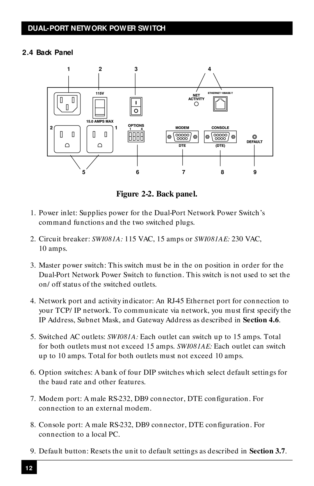
Figure 2-2. Back panel.
1.Power inlet: Supplies power for the
2.Circuit breaker: SWI081A: 115 VAC, 15 amps or SWI081AE: 230 VAC, 10 amps.
3.Master power switch: This switch must be in the on position in order for the
4.Network port and activity indicator: An
5.Switched AC outlets: SWI081A: Each outlet can switch up to 15 amps. Total
for both outlets must not exceed 15 amps. SWI081AE: Each outlet can switch up to 10 amps. Total for both outlets must not exceed 10 amps.
6.Option switches: A bank of four DIP switches which select default settings for the baud rate and other features.
7.Modem port: A male
8.Console port: A male
9.Default button: Resets the unit to default settings as described in Section 3.7.
12